
Air-cooling and water-cooling dual-purpose heat sink

A radiator and water-cooling technology, applied in the direction of cooling/ventilation/heating transformation, electrical components, electrical equipment structural parts, etc., can solve the problems of limited application range of heat pipe heat dissipation technology, single heat dissipation method, and inability to meet the use requirements, etc.

Pending Publication Date: 2018-05-04
SHENZHEN HOHOMER DIGITAL POWER TECH CO LTD
View PDF19 Cites 3 Cited by
  • Summary
  • Abstract
  • Description
  • Claims
  • Application Information

AI Technical Summary

Problems solved by technology

For several single cooling methods, water cooling has a good heat dissipation effect, but it takes up space and increases weight; forced air cooling technology has a better heat dissipation effect, but it needs to arrange fans and also takes up space; natural cooling is suitable for small spaces, but the heat dissipation effect is poor; The application range of heat pipe cooling technology is limited, and the cost of micro-channel technology is relatively high
Now high-power electric vehicles, forklifts and other heavy vehicles are widely used, and the power of the motor electronic control system has increased, but the existing heat dissipation technology can no longer meet the requirements, and it is necessary to pursue a heat dissipation device with higher performance; in addition, in general, the heat dissipation of the controller can only Choose a cooling method instead of changing the heat dissipation method according to the usage situation and power adjustment. For the situation where the power of modern cars varies greatly, a single heat dissipation method can no longer meet the use requirements.

Method used


Image

  • Air-cooling and water-cooling dual-purpose heat sink
  • Air-cooling and water-cooling dual-purpose heat sink
  • Air-cooling and water-cooling dual-purpose heat sink

Examples


Embodiment Construction

[0017] The present invention will be described in further detail below in conjunction with the embodiments and with reference to the accompanying drawings.

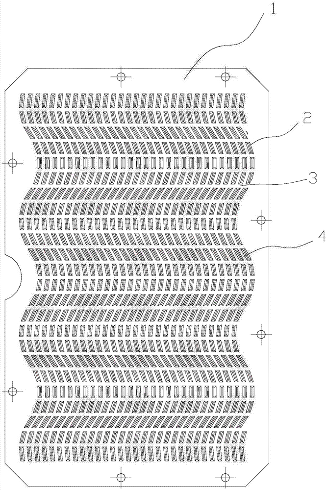
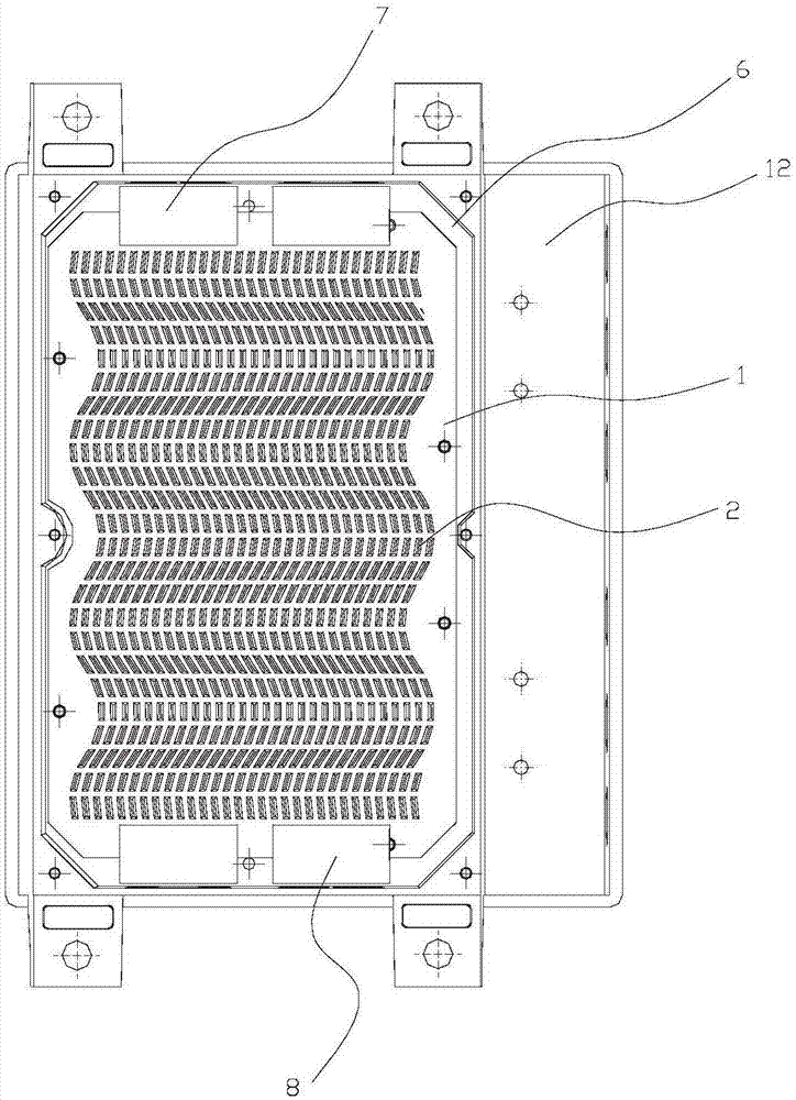
[0018] For an air-cooled and water-cooled dual-purpose radiator in this embodiment, please refer to the attached Figure 1 to Figure 5 , including a substrate 1, one side of the substrate 1 protrudes outward to form a heat conducting surface 5 in close contact with the heating element 12, and the other side of the substrate 1 extends upwards with a plurality of strip fins 2, the strip fins 2 Arranged on the substrate 1 to form a plurality of parallel wavy channels 4 from top to top, the strip fins 2 are arranged on the substrate 1 to form a plurality of parallel linear channels 3 from left to right, the substrate 1 The outer frame surrounding the strip fins 2 can also be detachably installed on the other side; the upper and lower ends of the outer frame can be respectively provided with an air-cooled outer frame 6 with fa...


PUM


Abstract

The invention discloses an air-cooling and water-cooling dual-purpose heat sink. The heat sink comprises a substrate, wherein one surface of the substrate bulges outwards to form a heat conducting surface tightly contacted with a heating element, the other surface of the substrate extends upwards to form multiple strip-shaped fins, the strip-shaped fins are arranged on the substrate to form multiple wave-shaped channels in parallel from bottom to top and multiple linear channels in parallel from left to right, and an outer frame surrounding the strip-shaped fins is detachably mounted on the other surface of the substrate; an air-cooling outer frame of fans and a water-cooling casing can be arranged at the upper end and the lower end of the outer frame respectively, the strip-shaped fins are sealed and surrounded by the water-cooling casing, and water pipe joints are arranged at the upper end and the lower end of the water-cooling casing respectively. The heat sink has the advantages ofbeing good in heat sinking effect and capable of realizing water-cooling or air-cooling heat sinking.

Description

technical field [0001] The invention relates to a heat dissipation element, in particular to an air-cooled and water-cooled dual-purpose radiator which has good heat dissipation effect and can realize water-cooled heat dissipation or air-cooled heat dissipation. Background technique [0002] The existing technology provides several single cooling methods for the heat dissipation of the controller, including water cooling technology, forced air cooling technology, natural cooling, heat pipe heat dissipation and micro-channel heat dissipation, etc., which are selected according to the actual use situation. Water cooling is used for high-power heat dissipation. Forced air cooling is suitable for open spaces, natural cooling is used for small power components, and heat pipe and microchannel technology are suitable for special cases. For several single cooling methods, water cooling has a good heat dissipation effect, but it takes up space and increases weight; forced air cooling...

Claims


Application Information

Patent Timeline
IPC IPC(8): H05K7/20
CPCH05K7/20854H05K7/20863H05K7/20872
Inventor 余得贵闫伟伟
Owner SHENZHEN HOHOMER DIGITAL POWER TECH CO LTD
Learn More