
Container highway and railway transferring system

A container, road-rail technology, applied in the direction of hoisting device, storage device, hoisting device, etc., can solve the problems of low road-rail transfer efficiency and low utilization rate of workplace space.

Pending Publication Date: 2018-05-08
CRRC YANGTZE CO LTD
View PDF0 Cites 10 Cited by
  • Summary
  • Abstract
  • Description
  • Claims
  • Application Information

AI Technical Summary

Problems solved by technology

[0005] The invention provides a container road-rail transfer system, which solves or partially solves the technical problems in the prior art that the utilization rate of the working space of the container loading and unloading line of the electrified railway station is not high, and the efficiency of road-rail transfer is low

Method used


Image

  • Container highway and railway transferring system
  • Container highway and railway transferring system
  • Container highway and railway transferring system

Examples


Embodiment 1

[0104] Introduce the concrete structure of two-way side fetching device 4 in the present embodiment below:

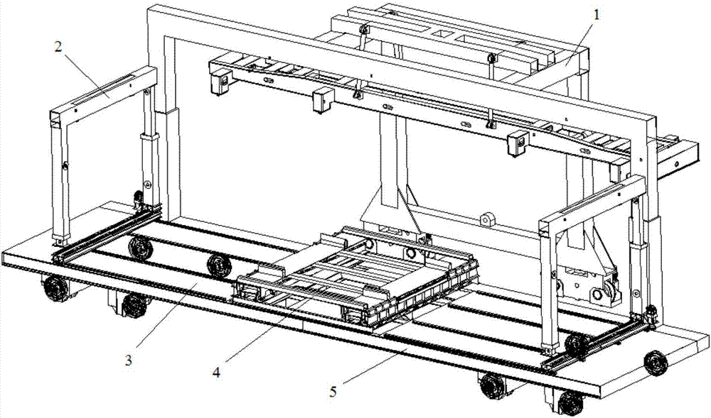
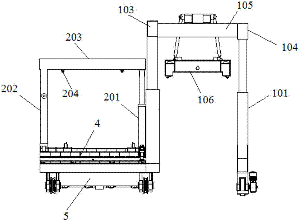
[0105] See attached Figure 12-20 The two-way side fetching device 4 includes: a bridge mechanism 402 and a tray mechanism 401, the tray mechanism 401 is slidably arranged on the bridge mechanism 402; the tray mechanism 401 can slide to the position corresponding to the card loading and unloading device 1, and / or, slide Move to the position corresponding to lifting device 2. The two-way side fetching device 4 also includes: a lifting mechanism 403, which is arranged below the bridge mechanism 402 and on the carrying platform 3, and is used to carry and drive the bridge mechanism 402 and the tray mechanism 401 to rise or fall.

[0106] The lifting mechanism 403 includes: a lifting platform 4031, 4 first telescopic cylinders 4032 and two first slideways 4033 arranged side by side. The 4 first telescopic cylinders 4032 are arranged at the bottom four corners of the liftin...

Embodiment 2

[0108] See attached Figure 19 , the lifting mechanism 403 also includes: 12 sets of first limit wheels 4035, 6 sets of first limit wheels 4035 are set on one first slideway 4033, and the two first limit wheels 4035 of each group are respectively arranged on the first On both sides of the slideway 4033, 12 sets of first limiting wheels 4035 can ensure that the bridge passing mechanism 402 at the upper end moves along a fixed straight line. There are at least two sets of first limiting wheels 4035 to play the role of fixed limiting in the bridge mechanism 402 .

[0109] A specific first slideway structure is introduced below:

Embodiment 3

[0111] The first slideway 4033 includes a plurality of first roller assemblies arranged side by side, and the first roller assembly includes: a first wheel seat fixed on the lifting platform 4031 and a first roller whose two ends are hinged on the first wheel seat , the bridge passing mechanism 402 slides on the first roller of the first slideway 4033 to reduce frictional resistance and ensure sufficient container transfer force.

[0112] Another specific structure of the first slideway 4033 is introduced below:


PUM


Abstract

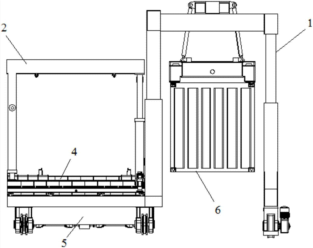
The invention relates to a container highway and railway transferring system. The container highway and railway transferring system comprises a lifting device, a bi-directional side taking device anda container lorry loading and unloading device. The bi-directional side taking device transfers containers corresponding to the position of the lifting device to the position corresponding to the container lorry loading and unloading device, and / or, transfers containers corresponding to the position of the container lorry loading and unloading device to the position corresponding to the lifting device; the lifting device lifts and puts containers on a railway vehicle onto the bi-directional side taking device, and / or lifts and puts the containers on the bi-directional side taking device to therailway vehicle; and the container lorry loading and unloading device lifts and puts the containers on a container lorry onto the bi-directional side taking device, and / or lifts and puts the containers on the bi-directional side taking device to the container lorry. According to the container highway and railway transferring system, it does not need to interfere with a railway electrified contactnet, the highway and railway transferring link is simplified, the equipment cost and the running cost are reduced, the space utilization rate of a work place is increased, and the highway and railwaytransferring efficiency is improved.

Description

technical field [0001] The invention relates to the technical field of container multimodal transport, in particular to a container road-rail transfer system. Background technique [0002] At present, the development level of multimodal transport in my country is still relatively low, and road transport has been the mainstay for a long time. Problems such as unsmooth coordination between road, railway and waterway transport, imperfect market environment, inadaptable regulations and standards, and lagging behind in the application of advanced technologies are more prominent. The volume of intermodal transport accounts for only 2.9% of the total freight volume of the whole society, which is far lower than the development level of the United States; the operation efficiency is not high, and the cost of cargo transit and transshipment accounts for about 30% of the entire logistics cost, resulting in the logistics cost of the whole country. Much higher than the logistics developed ...

Claims


Application Information

Patent Timeline
IPC IPC(8): B65G63/00B66C17/20B66C5/02B66C1/10B66F9/065B66F9/18B66F9/12B66F9/19B66F9/22
CPCB65G63/004B66C1/101B66C5/02B66C17/20B66F9/065B66F9/122B66F9/186B66F9/19B66F9/22
Inventor 张攀攀苏利杰梅琨林量才汤楚强刘凤伟黄美林沈鹏张华涛刘伟宋少波孙先俊刘爱文尹刚张楠彭全海黄恒王全虎
Owner CRRC YANGTZE CO LTD
Learn More