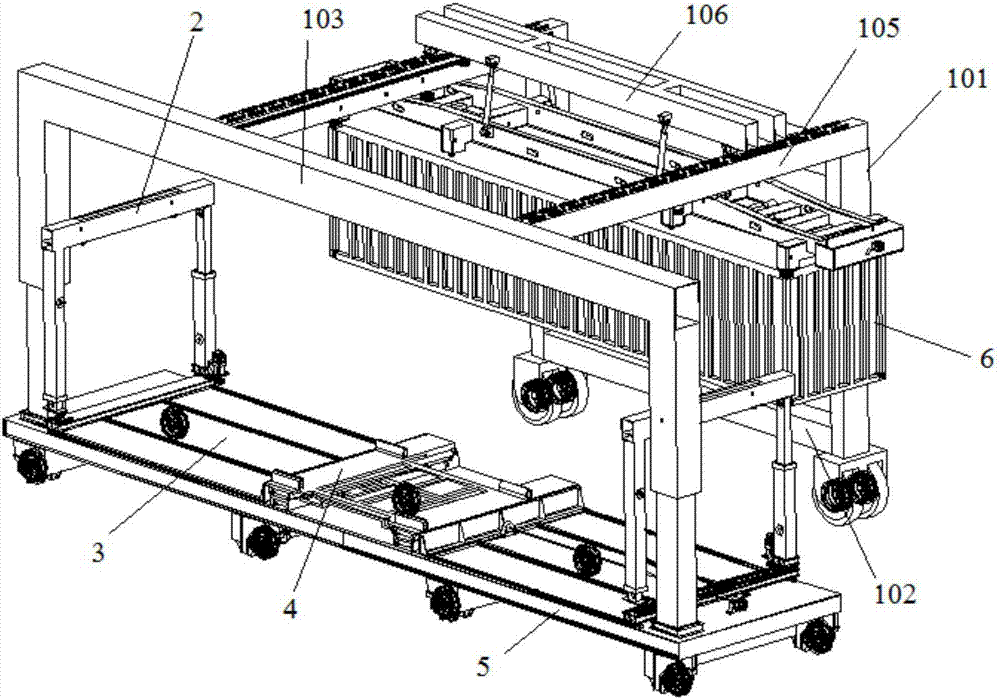
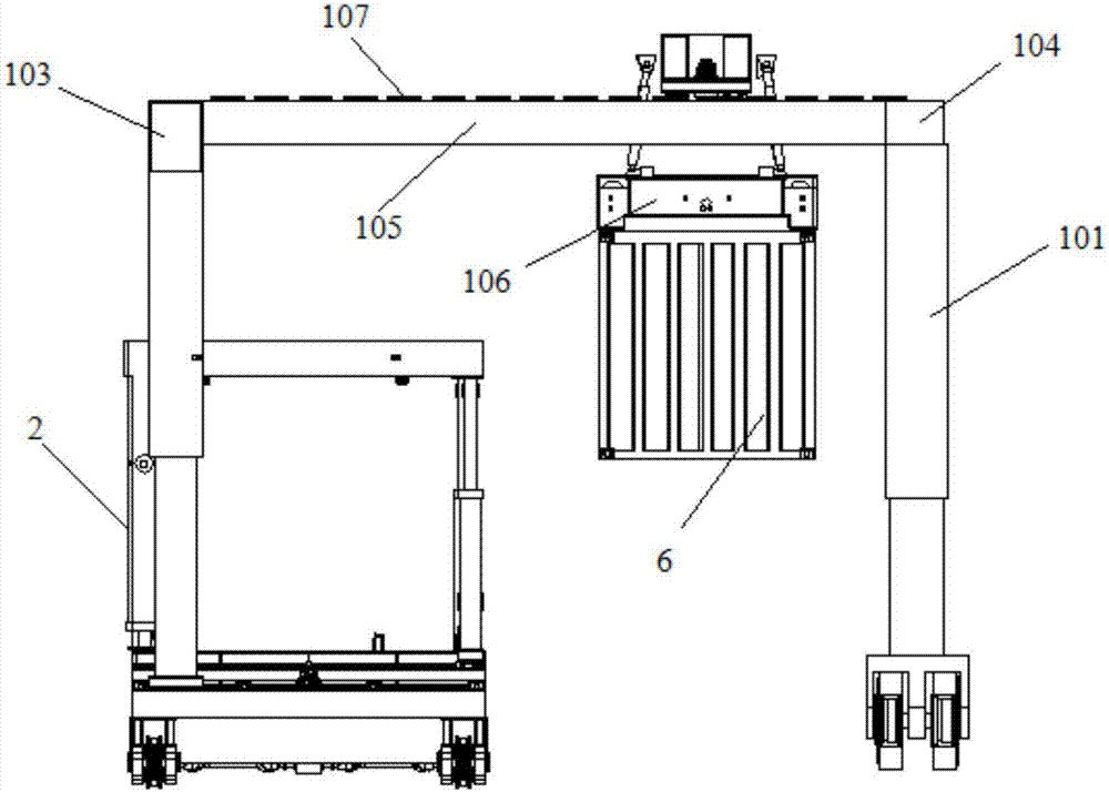
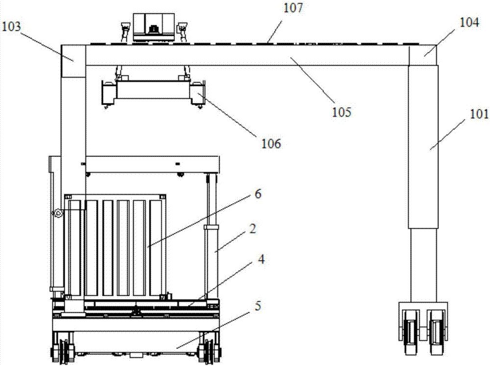
Container highway and railway transfer system
A container, road-rail technology, applied in the direction of hoisting device, storage device, hoisting device, etc., can solve the problems of low space utilization rate of the workplace, low efficiency of road-rail transfer, etc., to achieve convenient and quick lifting or lowering, avoiding interference Influence and accelerate the effect of lifting efficiency
- Summary
- Abstract
- Description
- Claims
- Application Information
AI Technical Summary
Problems solved by technology
Method used
Image

Examples
Embodiment 1
[0088] Introduce the specific structure of side fetching device 4 in the present embodiment below:
[0089] See attached Figures 10-18 , The side fetching device 4 includes: a bridge mechanism 402 and a tray mechanism 401 , the tray mechanism 401 is slidably disposed on the bridge mechanism 402 ; the tray mechanism 401 can slide to a position corresponding to the lifting device 2 . The side fetching device 4 also includes: a lifting mechanism 403 , which is arranged below the bridge mechanism 402 and on the carrying platform 3 , and is used to carry and drive the bridge mechanism 402 and the tray mechanism 401 to rise or fall.
[0090] See attached Figure 13 with 14 , the lifting mechanism 403 includes: a lifting platform 4031, 4 first telescopic cylinders 4032 and two first slideways 4033 arranged side by side, and the 4 first telescopic cylinders 4032 are arranged at the bottom four corners of the lifting platform 4031 for driving the lifting The platform 4031 rises or ...
Embodiment 2
[0092] See attached Figure 13 with 14 , the lifting mechanism 403 also includes: 12 sets of first limit wheels 4035, 6 sets of first limit wheels 4035 are set on one first slideway 4033, and the two first limit wheels 4035 of each group are respectively arranged on the first On both sides of the slideway 4033, 12 sets of first limiting wheels 4035 can ensure that the bridge passing mechanism 402 at the upper end moves along a fixed straight line. There are at least two sets of first limiting wheels 4035 to play the role of fixed limiting in the bridge mechanism 402 .
[0093] A specific first slideway structure is introduced below:
Embodiment 3
[0095] The first slideway 4033 includes a plurality of first roller assemblies arranged side by side, and the first roller assembly includes: a first wheel seat fixed on the lifting platform 4031 and a first roller whose two ends are hinged on the first wheel seat , the bridge passing mechanism 402 slides on the first roller of the first slideway 4033 to reduce frictional resistance and ensure sufficient container transfer force.
[0096] Another specific structure of the first slideway 4033 is introduced below:
PUM
 Abstract
Description
Claims
Application Information