Plasma cleaning and polishing device for ultra-high vacuum chamber

An ultra-high vacuum and plasma technology, applied in electrolysis components, electrolysis process, etc., can solve problems such as easy leakage, environmental pollution of waste liquid, incomplete cleaning, etc., and achieve the effects of avoiding radiation, safe operation, and even and thorough cleaning

Active Publication Date: 2020-02-04
TSINGHUA UNIV +1
View PDF10 Cites 0 Cited by
  • Summary
  • Abstract
  • Description
  • Claims
  • Application Information

AI Technical Summary

Problems solved by technology

[0003] In order to make the ultra-high vacuum system reach the required vacuum degree, it is necessary to ensure the cleanliness of the inner surface of the vacuum pipe or chamber. At present, the common method of cleaning the vacuum pipe or chamber is the combination of mechanical wire drawing and polishing and chemical cleaning. However, This method has the following disadvantages: (1) Mechanical wire drawing and polishing are easy to cause wear on the surface of the object to be cleaned, and the cleaning is not thorough, which cannot meet the requirements of high-cleanliness cleaning, and the labor intensity is relatively large, requiring the equipment to stop working. (2) Although the chemical cleaning method can prevent the surface of the object from being worn out, it needs to be cleaned repeatedly, and if the chemical cleaning solution is not selected properly, it will cause corrosion damage to the cleaning object, cause losses, and may also introduce new impurities. Moreover, the waste liquid discharged from chemical cleaning will cause environmental pollution, and improper handling of chemical agents will also cause harm to human health and safety.
[0004] For the plasma cleaning device in the prior art, it is mainly used to remove the water vapor inside the cavity with a small surface area, the power used is small, the discharge current is below 1mA, and the existing radio frequency discharge or microwave discharge plasma cleaning The structure of the device is complex, easy to leak, and easy to cause radiation to the environment and operators

Method used


Image

  • Plasma cleaning and polishing device for ultra-high vacuum chamber

Examples


Embodiment Construction

[0024] The technical solutions in the embodiments of the present invention will be clearly and completely described below in conjunction with the accompanying drawings in the embodiments of the present invention. Obviously, the described embodiments are only a part of the embodiments of the present invention, rather than all the embodiments. Based on the embodiments of the present invention, all other embodiments obtained by those of ordinary skill in the art without creative work shall fall within the protection scope of the present invention.

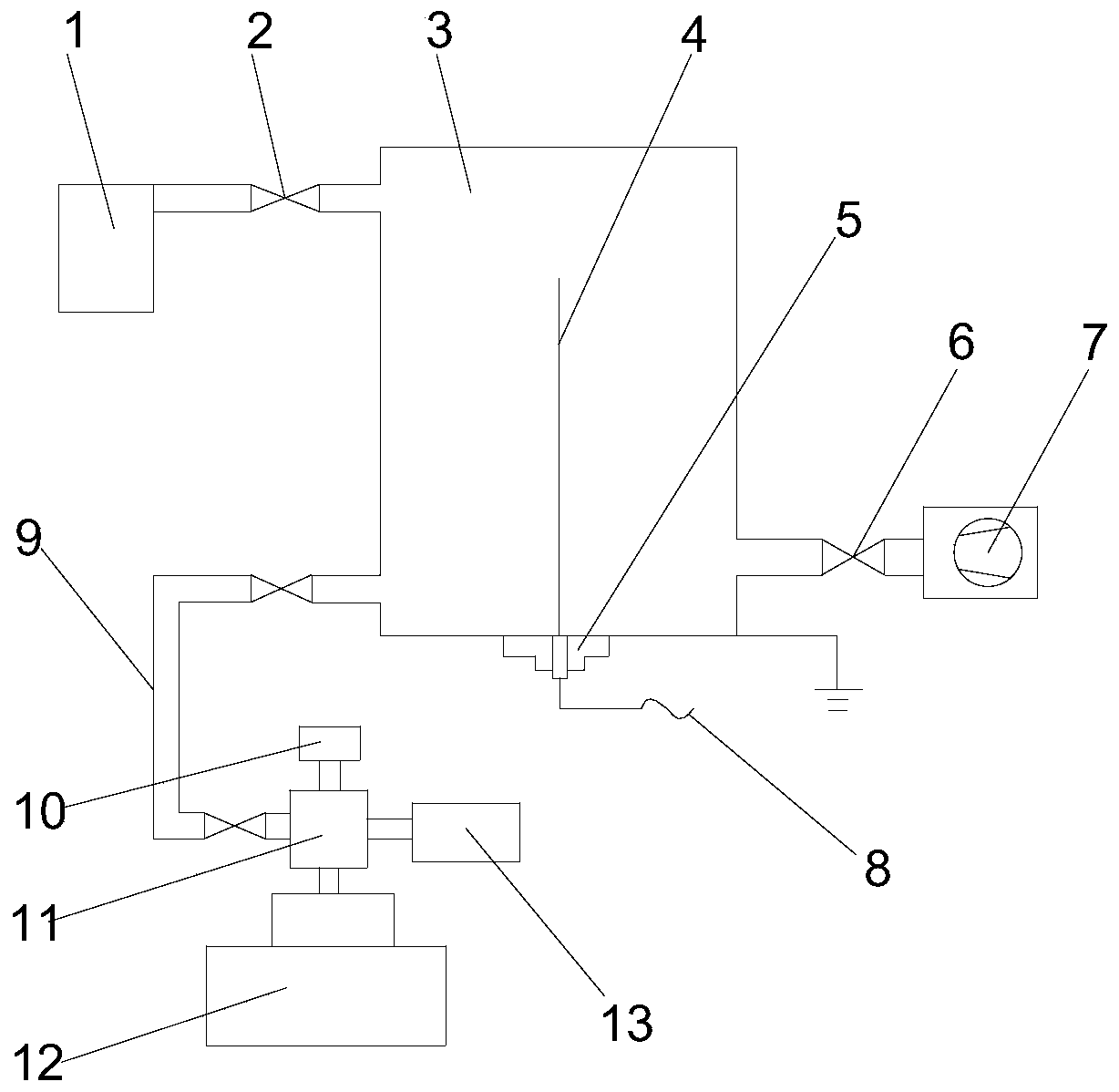
[0025] Such as figure 1 As shown, the present invention provides a plasma cleaning and polishing device for an ultra-high vacuum chamber, which includes a discharge electrode 4, a gas storage tank 1, and an air pump 7. The discharge electrode 4 is located in the ultra-high vacuum chamber to be cleaned. In the body 3, an electrode holder 5 is embedded on the bottom wall of the ultra-high vacuum chamber 3 to be cleaned, one end of the disc...


PUM

PropertyMeasurementUnit
diameteraaaaaaaaaa
lengthaaaaaaaaaa
diameteraaaaaaaaaa

Abstract

The invention provides a plasma cleaning and polishing device for an ultra-high vacuum chamber. The plasma cleaning and polishing device comprises a discharge electrode, a gas storage tank and an airpump. The discharge electrode is located in the ultra-high vacuum chamber to be cleaned. An electrode holder is embedded into the bottom wall of the ultra-high vacuum chamber to be cleaned. One end ofthe discharge electrode is inserted into the electrode holder. The electrode holder is electrically connected with a direct-current power source. The gas storage tank is connected with one end of theultra-high vacuum chamber to be cleaned. The air pump is connected with the other end of the ultra-high vacuum chamber to be cleaned. By the adoption of the plasma cleaning and polishing device for the ultra-high vacuum chamber, cleaning and polishing can be achieved under the condition that the inner wall of the ultra-high vacuum chamber is not damaged, and energy saving and environmental protection are achieved.

Description

Technical field [0001] The invention relates to the field of vacuum technology, in particular to a surface treatment device in an ultra-high vacuum cavity, and more specifically to a plasma cleaning and polishing device for an ultra-high vacuum cavity. Background technique [0002] At present, ultra-high vacuum system is the main place for modern workpiece surface analysis and research. It is also necessary to use ultra-high vacuum system in workpiece surface analysis technology: First, the low-energy electronic signal to be analyzed is easily scattered by residual gas molecules , So that the total signal of the spectrum is weakened. Only under ultra-high vacuum conditions, low-energy electrons can obtain a long enough mean free path without being lost by scattering; secondly, the ultra-high vacuum environment is the surface sensitivity of surface analysis technology. Required, in 10 -6 Under the high vacuum of mbar, a single layer of gas will be adsorbed on the solid surface in ...

Claims


Application Information

Patent Timeline
Patent Type & Authority Patents(China)
IPC IPC(8): C25F3/16C25F7/00
CPCC25F3/16C25F7/00
Inventor 刘大猛张晨辉王婷雒建斌赵嘉峰欧宏炜鹿建王艳会
Owner TSINGHUA UNIV
Why Eureka
Try Eureka