Hydraulic cooling device

A cooling device and hydraulic technology, applied in the direction of fluid pressure actuation device, fluid pressure actuation system components, mechanical equipment, etc., can solve the assembly and maintenance/repair difficulties of hydraulic oil cooling device, the reduction of system volume efficiency, and the lack of compactness of the system. and other problems, to achieve the effect of compact structure, sufficient cooling air volume and small space occupation

Pending Publication Date: 2018-05-08
陕西德立机电科技有限公司
View PDF1 Cites 4 Cited by
  • Summary
  • Abstract
  • Description
  • Claims
  • Application Information

AI Technical Summary

Problems solved by technology

[0002] During the operation of the hydraulic system, part of the hydraulic energy is converted into heat energy due to the resistance loss along the way of the oil, the local pressure loss and the mechanical friction loss of the components. If this part of energy cannot be released in time, the hydraulic system will generate corresponding Temperature rise, and the rise of system temperature will lead to the decrease of volumetric efficiency of the system, excessive oil oxidation and other unfavorable phenomena. At this time, it is necessary to connect this device to the system to take away excess heat, so as to maintain the system temperature Within a certain range
When the power of the whole machine is small, or the energy loss is small, the usual practice is to connect an air cooler in series on the system oil return or hydraulic pump drain pipeline, and the air cooler is driven by an independent motor, so that Not only the cost is high, but also the system is not compact enough and takes up a lot of space
[0003] The existing published unauthorized Chinese patent document CN 104100605 A discloses a hydraulic cooling device, which mainly solves the problem that the heat exchange tube is located inside the hydraulic machine, and the hydraulic oil cooling device must be difficult to assemble and maintain / repair

Method used


Image

  • Hydraulic cooling device
  • Hydraulic cooling device
  • Hydraulic cooling device

Examples


Embodiment Construction

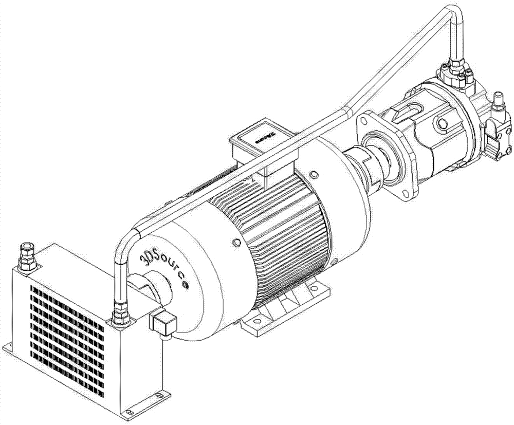
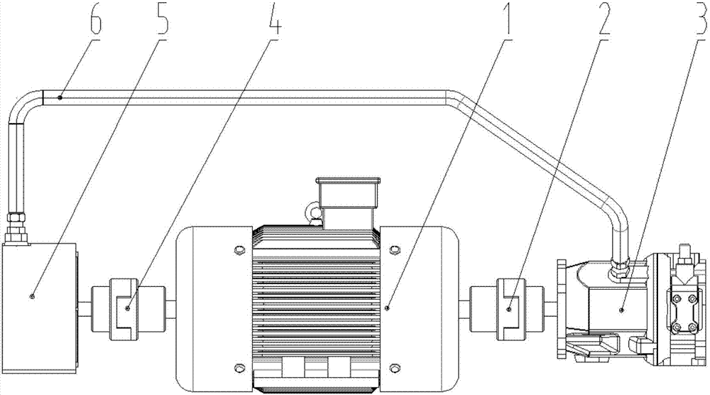
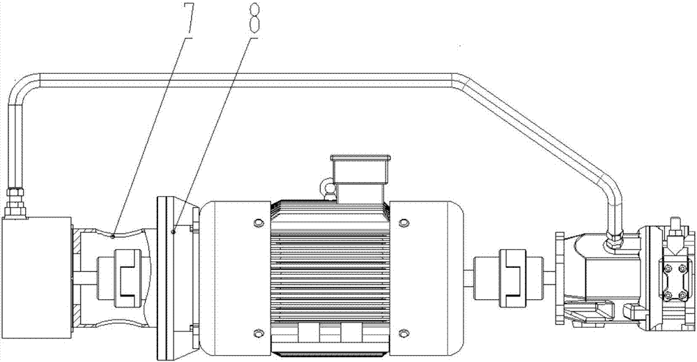
[0030] Such as Figure 1-3 The shown hydraulic cooling device includes a double-head motor 1, one end of the double-head motor 1 is connected to the hydraulic pump 3 through the first coupling 2, and the other end is connected to the air cooler 5 through the second coupling 4, so The air cooler 5 is connected to one end of the oil delivery pipeline 6 , and the other end of the oil delivery pipeline 6 is connected to the hydraulic pump 3 .

[0031] Such as Figure 4-7 As shown, the air cooler 5 includes a housing 51 and a bottom plate 54, the two sides of the top of the housing 51 are provided with an oil inlet 56 and an oil outlet 57, and the inside of the housing 51 is connected to the oil inlet 56 and the outlet. The vertical direction of the oil port 57 communication position is provided with several layers of parallel heat dissipation hollow plates 52; the inside of the air cooler 5 is provided with a fan device 55 adjacent to the heat dissipation hollow plate 52, and the...


PUM


Abstract

The invention relates to a hydraulic cooling device. The hydraulic cooling device comprises a double-head motor; one end of the double-head motor is connected with a hydraulic pump through a first coupler, and the other end of the double-head motor is connected with an air cooling machine through a second coupler; the air cooling machine is connected with one end of an oil conveying pipeline; andthe other end of the oil conveying pipeline is connected with a hydraulic pump. The hydraulic cooling device has the beneficial effects that by using the double-head motor, the air cooling machine isdriven to run while the hydraulic pump is driven, it is not needed to additionally arrange a motor for the air cooling machine, and the hydraulic system cost is reduced; and a new structure is adoptedfor a fan device of the air cooling machine, running is stable, the cooling air volume is sufficient, the structure is compact, and the occupied space is small.

Description

technical field [0001] The invention relates to a device for cooling hydraulic oil, in particular to a hydraulic cooling device. Background technique [0002] During the operation of the hydraulic system, part of the hydraulic energy is converted into heat energy due to the resistance loss along the way of the oil, the local pressure loss and the mechanical friction loss of the components. If this part of energy cannot be released in time, the hydraulic system will generate corresponding Temperature rise, and the rise of system temperature will lead to the decrease of volumetric efficiency of the system, excessive oil oxidation and other unfavorable phenomena. At this time, it is necessary to connect this device to the system to take away excess heat, so as to maintain the system temperature Within a certain range. When the power of the whole machine is small, or the energy loss is small, the usual practice is to connect an air cooler in series on the system oil return or h...

Claims


Application Information

Patent Timeline
Patent Type & Authority Applications(China)
IPC IPC(8): F15B21/04
CPCF15B21/042
Inventor 王海飞
Owner 陕西德立机电科技有限公司
Why Eureka
Try Eureka