Star wheel reducer and mechatronics equipment with the star wheel reducer

A star wheel reducer and star wheel technology, applied in the field of reducer, can solve the problems of limited life of the flexible wheel of the harmonic reducer, increase the number of gears, and high production cost, achieve broad application prospects, ensure transmission ratio, structure simple effect

Inactive Publication Date: 2019-03-05
深圳市星轮科技有限公司
View PDF7 Cites 0 Cited by
  • Summary
  • Abstract
  • Description
  • Claims
  • Application Information

AI Technical Summary

Problems solved by technology

[0004] However, the flexspline of the harmonic reducer must be made of special materials to ensure its life because it must withstand high-frequency elastic deformation. Therefore, it is more difficult to process small modulus tooth shapes on this material, and even so, The life of the flexible spline of the harmonic reducer is still limited, and it needs to be replaced more frequently, which further increases the cost
Due to the limitations of the design of the cycloidal pin gear tooth profile, the RV reducer cannot achieve the high reduction ratio of the harmonic gear in the first-stage transmission, so it is necessary to add an additional stage of planetary gear train transmission, which not only increases the number of gears, but also increases the number of gears. The complexity of the structure is increased, and the cost is also greatly increased
[0005] It can be seen that the structure of the harmonic star gear reducer and the RV reducer itself is more complicated, and the production cost is higher

Method used


Image

  • Star wheel reducer and mechatronics equipment with the star wheel reducer
  • Star wheel reducer and mechatronics equipment with the star wheel reducer
  • Star wheel reducer and mechatronics equipment with the star wheel reducer

Examples


Embodiment Construction

[0033] The technical solutions in the embodiments of the present invention will be clearly and completely described below in conjunction with the accompanying drawings in the embodiments of the present invention. Obviously, the described embodiments are only a part of the embodiments of the present invention, rather than all the embodiments. Based on the embodiments of the present invention, all other embodiments obtained by those of ordinary skill in the art without creative work shall fall within the protection scope of the present invention.

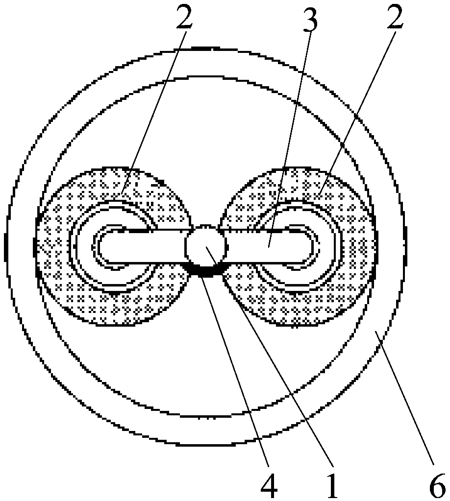
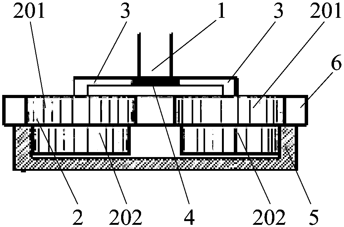
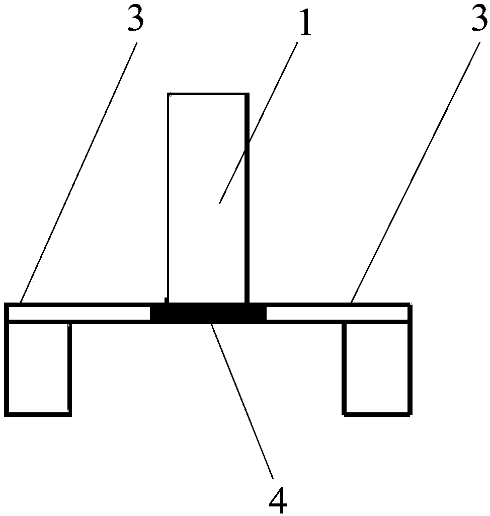
[0034] The core of the present invention is to provide a star gear reducer, which can ensure the transmission ratio and has a simple structure. Another core of the present invention is to provide a mechatronics device including the above-mentioned star gear reducer, which can ensure the transmission ratio and has a simple structure.

[0035] In the first specific embodiment of the star gear reducer provided by the present invention, it inc...


PUM


Abstract

The invention discloses a planetary wheel speed reducer. The planetary wheel speed reducer comprises a main shaft connected with a high-speed part, planetary wheels, a fixed inner tooth ring fixedly arranged, and an output inner tooth ring connected with a low-speed part. The axes of the planetary wheels are eccentric relative to the axis of the main shaft and are arranged in parallel. Center shafts in the planetary wheels are connected to the main shaft, and the planetary wheels can rotate around the respective center shafts in the planetary wheels. Each planetary wheel comprises a first-stage gear used for meshing transmission with the fixed inner tooth ring and a second-stage gear used for meshing transmission with the output inner tooth ring. In each planetary wheel, the first-stage gear is coaxially and fixedly arranged on one side of the second-stage gear. The planetary wheels in the planetary wheel speed reducer conduct a circular movement around the main shaft and a rotation movement, the two movements are superimposed and transmitted to the output inner tooth ring, and thus the planetary wheel speed reducer has a large transmission ratio, and the planetary wheel speed reducer is simple in structure and convenient to machine. The invention further discloses mechanical and electronic integration equipment comprising the planetary wheel speed reducer, and the planetary wheel speed reducer can guarantee the transmission ratio and is simple in structure.

Description

Technical field [0001] The invention relates to the technical field of speed reducers, in particular to a star gear reducer. In addition, the present invention also relates to a mechatronic equipment including the above-mentioned star gear reducer. Background technique [0002] The differential gear reduction mechanism is the most advanced robot reducer today, which mainly includes RV reducer and harmonic reducer. Its principle is to use the internal and external gears with a small number of teeth to mesh with a special non-fixed shaft external gear movement. Great reduction ratio between input and output. Differential gear reduction mechanisms can often achieve large transmission ratios in limited space and transmission stages, and are widely used in high-end fields such as medical treatment, CNC machine tools, automobile manufacturing, robotics, and aerospace. [0003] The RV reducer is driven by the first-stage planetary gear train to drive the second-stage cycloid pin wheel, ...

Claims


Application Information

Patent Timeline
Patent Type & Authority Patents(China)
IPC IPC(8): F16H1/32F16H57/023
CPCF16H1/32F16H57/023
Inventor 李诗濛
Owner 深圳市星轮科技有限公司
Why Eureka
Try Eureka