Combustor for gas stove

A burner and gas stove technology, which is applied in the field of gas stoves, can solve problems such as hindering the improvement of burner combustion efficiency, reducing yield, and reducing combustion efficiency, and achieves the effect of facilitating flow, replenishment, and improving combustion efficiency

Pending Publication Date: 2018-05-08
NINGBO FOTILE KITCHEN WARE CO LTD
View PDF0 Cites 7 Cited by
  • Summary
  • Abstract
  • Description
  • Claims
  • Application Information

AI Technical Summary

Problems solved by technology

[0002] The existing burner includes a base, a gas mixing chamber, an outer ring fire cover and an inner ring fire cover, wherein the gas mixing chamber is arranged above the base, and the outer ring fire cover and the inner ring fire cover are arranged on the side of the gas mixing chamber. Above, the space between the outer ring fire cover and the inner ring fire cover is limited, and it is relatively closed in the horizontal direction, resulting in insufficient flow and heat exchange of high-temperature gas inside, which hinders the improvement of the combustion efficiency of the burner
[0003] In addition, at present, the fire cover of the burner is generally made of copper casting. This kind of fire cover has the advantages of low processing technology requirements, easy transportation and storage, etc., but it is easy to generate air bubbles during the casting process and cause quality problems, thereby reducing the yield. In addition, it also has the following problems: copper is a good conductor of heat, with a large thermal conductivity and fast heat conduction. When the primary air volume is large, or when the flame burns near the fire hole, tempering is prone to occur, and part of the heat will pass through the furnace during combustion. The fire cover is transmitted to the base of the burner, which will not only reduce the combustion efficiency, but also increase the temperature of the base, and the cast iron made of the base is easily oxidized and corroded at high temperature and a loose oxide layer is formed on the surface , thereby affecting its service life

Method used


Image

  • Combustor for gas stove
  • Combustor for gas stove
  • Combustor for gas stove

Examples


Embodiment 2

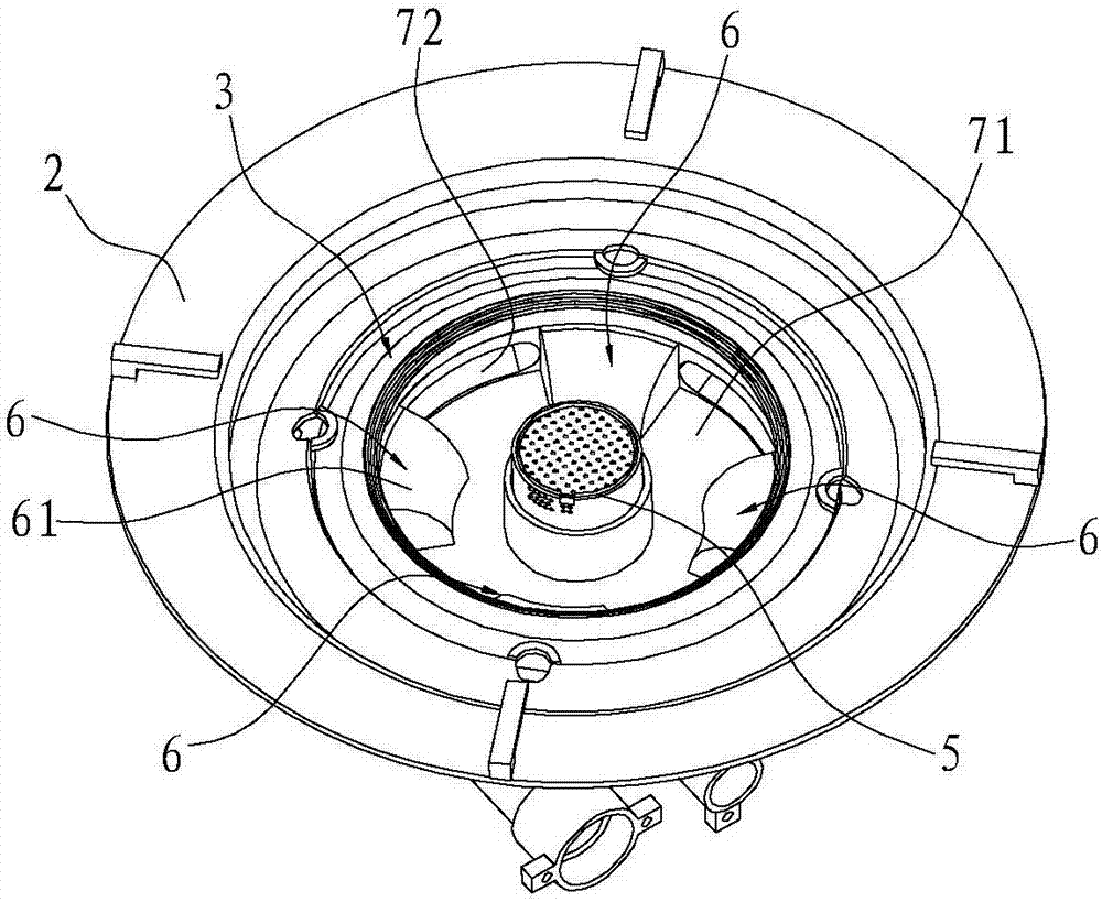
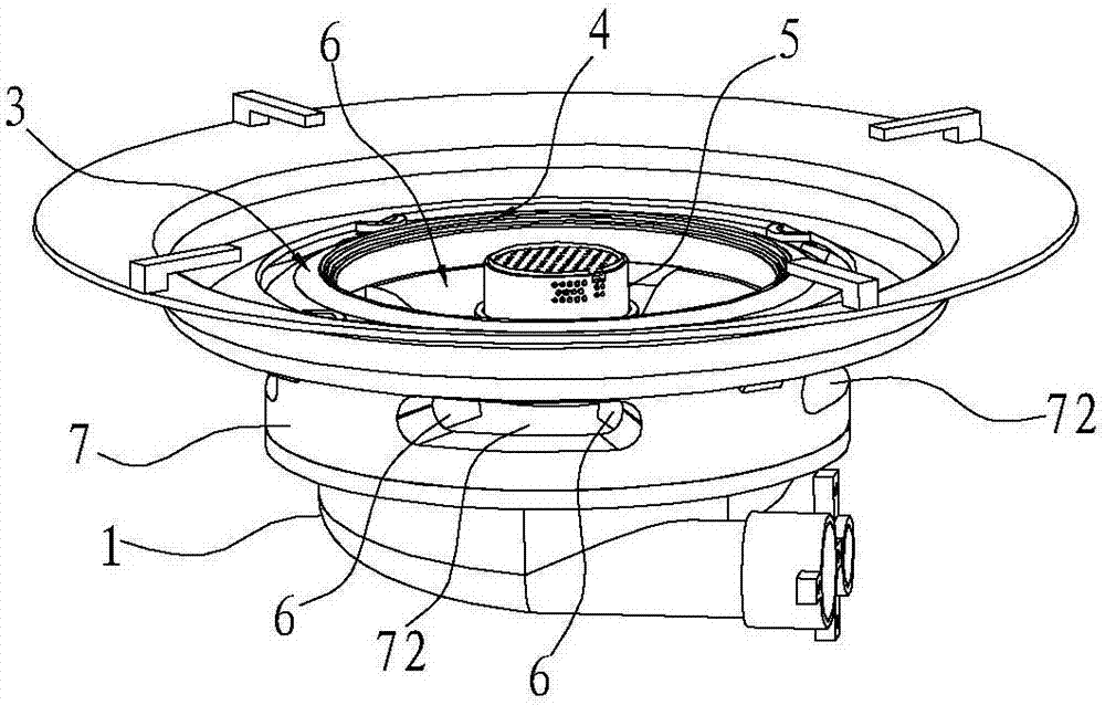
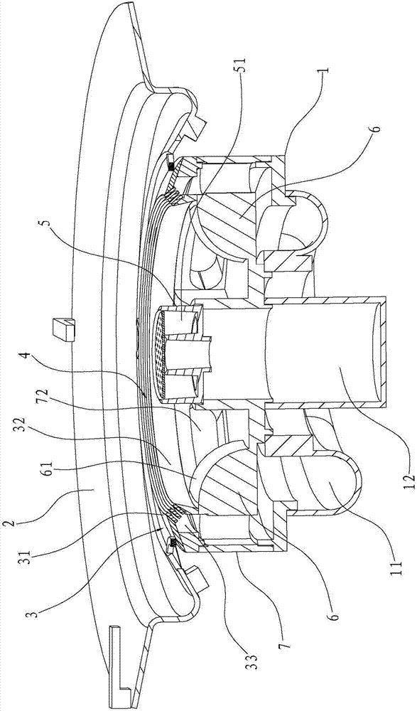
[0032] Such as Figure 7 and Figure 8 As shown, the difference from Embodiment 1 is that the turbulent body 6 in this embodiment is in the form of a sheet and is two pieces, the longitudinal section of each turbulent body 6 is arc-shaped, and the upper end of each turbulent body 6 is fixed to the lower end of the outer ring wall , and its lower end is fixed on the bottom surface of the annular chamber 71. Further, the outer side of each disruptor 6 constitutes the above-mentioned first side 61 , and the radian of the first side 61 is R5˜R200 (preferably R90).

Embodiment 3

[0034] Such as Figure 9 and Figure 11 As shown, different from Embodiment 2, in this embodiment, the longitudinal section of the installation port 30 increases evenly from the inside to the outside, that is, the installation port 30 is flared from the inside to the outside, so that the fire outlet can be effectively adjusted. The gas velocity at the place can effectively avoid the phenomenon of leaving the flame and tempering.

Embodiment 4

[0036] Such as Figure 10 and Figure 12 As shown, the difference from Embodiment 2 is that in this embodiment, the longitudinal section of the installation port 30 becomes smaller evenly from the inside to the outside, that is, the installation port 30 is in the shape of a neck from the inside to the outside, thereby speeding up the fire outlet. The speed of the gas increases the power of the gas, which in turn drives the power of the air at the fire outlet, making the entire combustion more complete.


PUM


Abstract

The invention relates to a combustor for a gas stove. The combustor comprises a base, a gas mixing chamber, an inner ring fire cover and an outer ring fire cover; the gas mixing chamber is arranged above the base, and is provided with an annular cavity; the inner ring fire cover and the outer ring fire cover are arranged above the gas mixing chamber, and are positioned on the inner and outer sidesof the annular cavity; secondary air holes are formed in the side part of the gas mixing chamber, and communicates with the annular cavity to form a secondary air channel; at least two spoilers are arranged in the annular cavity in the peripheral direction; intake gaps are formed between the adjacent spoilers; and each intake gap is opposite to the corresponding secondary air hole. Compared withthe prior art, through design of the spoilers, air fed from the secondary air holes and high-temperature gas near fire outlets of the outer ring fire cover and the inner ring fire cover can be disturbed, so that flowing and heat exchange of the high-temperature gas are facilitated, supply of secondary air is facilitated, and the combustion efficiency is improved.

Description

technical field [0001] The invention relates to the field of gas stoves, in particular to a burner for a gas stove. Background technique [0002] The existing burner includes a base, a gas mixing chamber, an outer ring fire cover and an inner ring fire cover, wherein the gas mixing chamber is arranged above the base, and the outer ring fire cover and the inner ring fire cover are arranged on the side of the gas mixing chamber. Above, the space between the outer ring fire cover and the inner ring fire cover is limited and relatively closed in the horizontal direction, resulting in insufficient flow and heat exchange of high-temperature gas inside, hindering the improvement of the combustion efficiency of the burner. [0003] In addition, at present, the fire cover of the burner is generally made of copper casting. This kind of fire cover has the advantages of low processing technology requirements, easy transportation and storage, etc., but it is easy to generate air bubbles ...

Claims


Application Information

Patent Timeline
Patent Type & Authority Applications(China)
IPC IPC(8): F23D14/46F23D14/70F23L9/00
CPCF23D14/46F23D14/70F23L9/00
Inventor 苏慧玲茅忠群诸永定郑军妹
Owner NINGBO FOTILE KITCHEN WARE CO LTD
Why Eureka
Try Eureka