Optical alignment method for liquid crystal display panel

A liquid crystal display panel and optical alignment technology, which is applied in optics, nonlinear optics, instruments, etc., can solve problems such as uneven pretilt angle, lower product process yield, broken bright spots of liquid crystal display panel, etc., to avoid uneven angle The effect of uniformity, improving product process yield, and reducing the difference between alignment voltage and UV light intensity

Active Publication Date: 2018-05-08
TCL CHINA STAR OPTOELECTRONICS TECH CO LTD
View PDF6 Cites 4 Cited by
  • Summary
  • Abstract
  • Description
  • Claims
  • Application Information

AI Technical Summary

Problems solved by technology

In the actual process, the size of the pretilt angle is mainly affected by three factors: alignment voltage (CuringVoltage), alignment time length (Curing Time), and UV light intensity. In different process lines, due to differences in machines, the same The actual alignment voltage and UV light intensity of each machine under the alignment parameters are still different, resulting in uneven pretilt angles of the product, resulting in problems such as broken bright spots on the LCD panel, and reducing the product process yield.

Method used


Image

  • Optical alignment method for liquid crystal display panel
  • Optical alignment method for liquid crystal display panel

Examples


Embodiment Construction

[0039] In order to further illustrate the technical means adopted by the present invention and its effects, the following describes in detail in conjunction with preferred embodiments of the present invention and accompanying drawings.

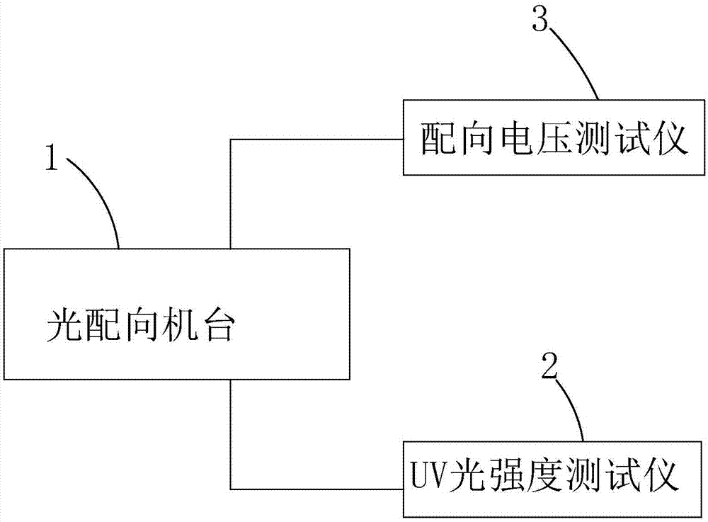
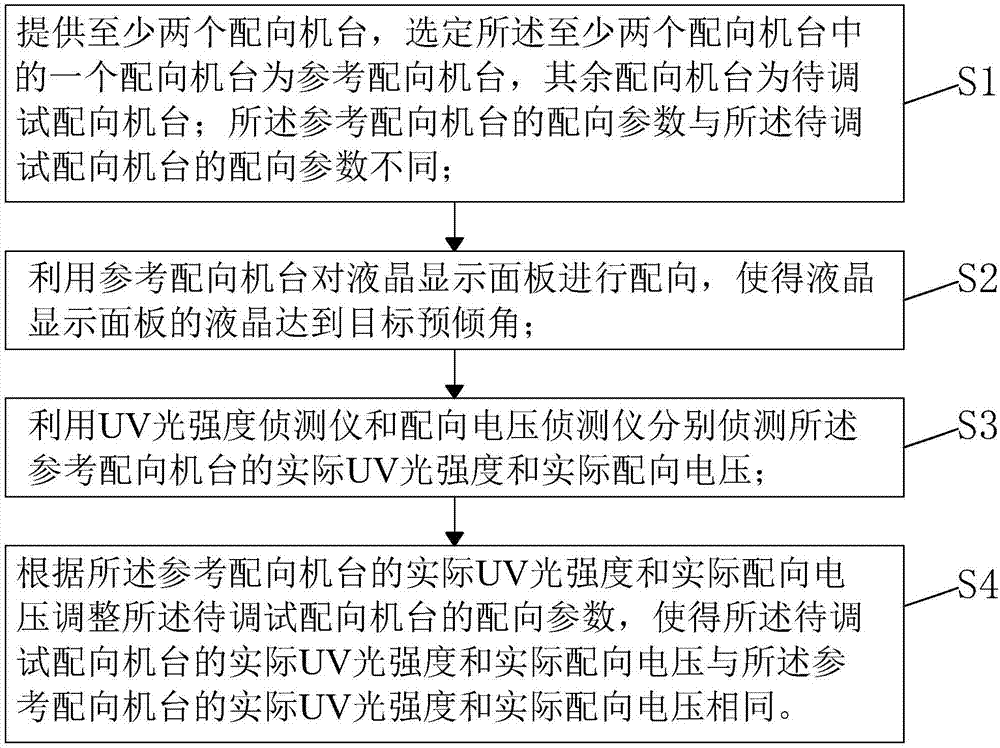
[0040] see figure 1 and figure 2 , the invention provides a method for aligning a liquid crystal display panel, comprising the following steps:

[0041] Step S1, providing at least two alignment machines 1, selecting one of the at least two alignment machines 1 as a reference alignment machine, and the other alignment machines 1 as alignment machines to be debugged; The alignment parameters of the reference alignment machine are different from the alignment parameters of the alignment machine to be debugged.

[0042] Specifically, the difference between the alignment parameters of the reference alignment machine and the alignment parameters of the alignment machine to be debugged means that the reference alignment machine makes the alignmen...


PUM


Abstract

The invention provides an optical alignment method for a liquid crystal display panel. The method comprises: using a UV light intensity detector and an alignment voltage detector to respectively detect actual UV light intensity and actual alignment voltage which make liquid crystal of a liquid crystal display panel of a reference alignment machine reach a target pretilt angle, and according to theactual UV light intensity and actual alignment voltage of the reference alignment machine, adjusting alignment parameters of a to-be-debugged alignment machine, to make the actual UV light intensityand actual alignment voltage of the to-be-debugged alignment machine be same with the actual UV light intensity and actual alignment voltage of the reference alignment machine. The method can reduce differences of the alignment voltage and UV light intensity of the alignment machines, and prevent phenomenon of non-uniform angles of the pretilt angles of the liquid crystal display panels, and improve product process yield.

Description

technical field [0001] The invention relates to the field of display technology, in particular to an optical alignment method of a liquid crystal display panel. Background technique [0002] Liquid Crystal Display (LCD) has many advantages such as thin body, power saving, and no radiation, and has been widely used, such as LCD TV, mobile phone, personal digital assistant, digital camera, computer screen or notebook computer screen, etc. . [0003] Most of the existing liquid crystal displays are backlight liquid crystal displays, which include a housing, a liquid crystal panel disposed in the housing, and a backlight module disposed in the housing. Generally, a liquid crystal panel is composed of a color filter substrate (Color Filter, CF), a thin film transistor array substrate (Thin Film Transistor Array Substrate, TFT Array Substrate), and a liquid crystal layer (Liquid Crystal Layer) filled between the two substrates. , its working principle is to control the rotation ...

Claims


Application Information

Patent Timeline
Patent Type & Authority Applications(China)
IPC IPC(8): G02F1/1337
CPCG02F1/133788
Inventor 赵丽
Owner TCL CHINA STAR OPTOELECTRONICS TECH CO LTD
Why Eureka
Try Eureka