Machine-vision-based workpiece detection method and system

A workpiece detection and machine vision technology, which is applied to computer parts, instruments, measuring devices, etc., can solve the problems of high requirements on workpiece angles and positions, unsatisfactory realization, and unsatisfactory process effects, and achieves low cost and good quality. Detection effect, good effect

Pending Publication Date: 2018-05-08
宁波蓝圣智能科技有限公司
View PDF7 Cites 17 Cited by
  • Summary
  • Abstract
  • Description
  • Claims
  • Application Information

AI Technical Summary

Problems solved by technology

[0010] The technical problem to be solved by the present invention lies in the defects existing in the workpiece detection in the prior art, such as high requirements on the angle and position of the workpiece, the process effect is not ideal; the realization is not very ideal in the case of occlusion; the implementation process is complicated , the effect is not good, etc.

Method used


Image

  • Machine-vision-based workpiece detection method and system
  • Machine-vision-based workpiece detection method and system
  • Machine-vision-based workpiece detection method and system

Examples


Embodiment 1

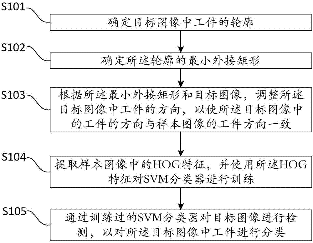
[0060] This embodiment provides a workpiece detection method based on machine vision, the flow chart of which is as follows figure 1 As shown, the details are as follows:

[0061] Step S101, determining the contour of the workpiece in the target image.

[0062] Among them, the target image comes from the camera device of the industrial robot. The imaging process of the imaging device is continuous; therefore, in the present invention, the process of processing the target image is also continuous.

[0063] The profile to which the present invention relates includes the profile of the outermost edge.

[0064] Obtain the outline of the outermost edge through the flood fill algorithm. The flood fill method, also known as the seed fill method, has many applications in graphics. The paint bucket tool of the "Paint" software under Windows is based on this algorithm. When you want to color a closed area or change the color in a closed area, the program automatically selects the are...

Embodiment 2

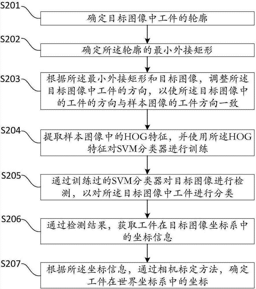
[0086] This embodiment provides a workpiece detection method based on machine vision, the flow chart of which is as follows figure 2 As shown, the details are as follows:

[0087] Step S201, determining the contour of the workpiece in the target image.

[0088] Step S202, determining the smallest circumscribed rectangle of the outline.

[0089] Step S203, adjusting the orientation of the workpiece in the target image according to the minimum circumscribed rectangle and the target image, so that the orientation of the workpiece in the target image is consistent with the orientation of the workpiece in the sample image.

[0090] Step S204, extracting HOG features in the sample image, and using the HOG features to train the SVM classifier.

[0091] In step S205, the target image is detected by the trained SVM classifier, so as to classify the artifacts in the target image.

[0092] Since steps S201 to S205 have been described in detail in Embodiment 1, details will not be rep...

Embodiment 3

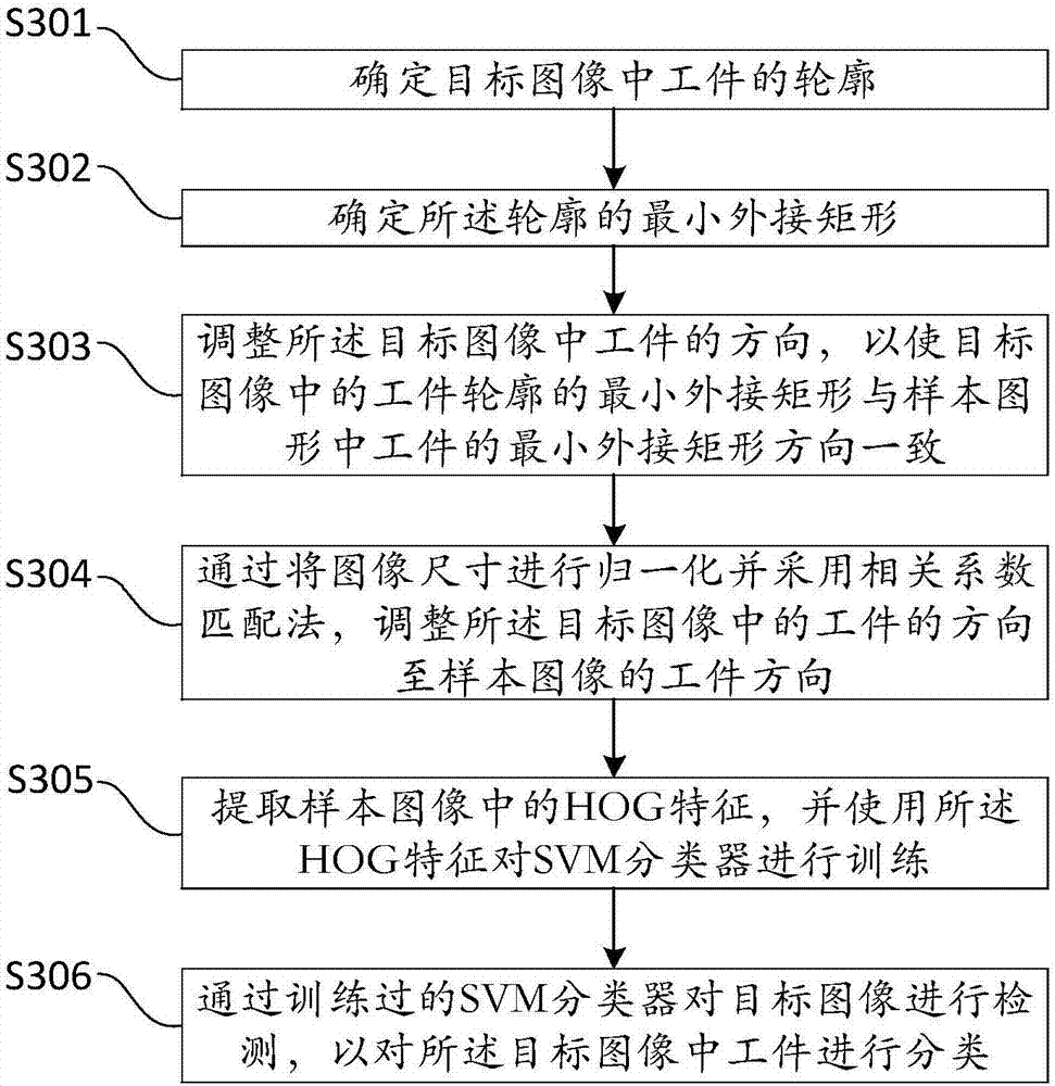
[0114] This embodiment provides a workpiece detection method based on machine vision, the flow chart of which is as follows image 3 , as detailed below:

[0115] Step S301, determining the contour of the workpiece in the target image.

[0116] Step S302, determining the smallest circumscribed rectangle of the outline.

[0117] Step S303 , adjusting the direction of the workpiece in the target image, so that the direction of the smallest circumscribed rectangle of the workpiece contour in the target image is consistent with the direction of the smallest circumscribed rectangle of the workpiece in the sample graphic.

[0118] Rotate the workpiece in the target image around the center of the rectangle until the direction of the smallest circumscribing rectangle of the workpiece outline in the target image is consistent with the direction of the smallest circumscribing rectangle of the workpiece in the sample graphic.

[0119] Since the rectangle is a centrally symmetrical figu...


PUM


Abstract

The invention, which relates to the technical field of the machine vision, discloses a machine-vision-based workpiece detection method and system. The workpiece detection method comprises: a contour of a workpiece in a target image is determined; a minimum circumscribed rectangle of the contour is determined; according to the minimum circumscribed rectangle and the target image, the direction of the workpiece in the target image is adjusted, so that the direction of the workpiece in the target image is consistent with the workpiece direction of a sample image; an HOG feature in the sample image is extracted and an SVM classifier is trained by using the HOG feature; and the target image is detected by using the trained SVM classifier to classify the workpiece in the target image. Accordingto the invention, a problem that the traditional industrial robot can not intelligently identify and locate the workpiece is solved; and with the machine vision algorithm, the workpiece is classifiedand located well. The method has no requirement on the attitude angle of the workpiece; and detection can be carried out continuously on the condition of shielding existence.

Description

technical field [0001] The invention relates to the technical field of machine vision, in particular to a machine vision-based workpiece detection method and system. Background technique [0002] With the advancement of science and technology, more and more industrial robots are being used in the production field to replace humans for repetitive production activities. [0003] An industrial robot is a multi-joint manipulator or a multi-degree-of-freedom machine device for the industrial field. It can perform work automatically and is a machine that realizes various functions by its own power and control capabilities. It can be commanded by humans or run according to pre-programmed programs. Modern industrial robots can also act according to the principles and programs formulated by artificial intelligence technology. [0004] In order to improve the degree of automation of industrial robots, industrial robots are required to be able to intelligently identify and locate work...

Claims


Application Information

Patent Timeline
Patent Type & Authority Applications(China)
IPC IPC(8): G06T7/564G06T7/30G06T7/00G06K9/62G01N21/88
CPCG06T7/0004G06T7/30G06T7/564G01N21/8851G01N2021/8887G06T2207/30164G06F18/2411
Inventor 彭成斌杨景翔徐显兵潘江锋王少剑康齐正吴宝国
Owner 宁波蓝圣智能科技有限公司
Why Eureka
Try Eureka