Exhaust gas treatment system and method

A waste gas treatment and waste gas technology, applied in separation methods, chemical instruments and methods, combined devices, etc., can solve problems such as unfavorable environmental protection, blockage of water pumps and water pipes, air pollution, etc., achieve simple structure, improve filtering effect, and increase contact area Effect

Inactive Publication Date: 2018-05-11
缪宜霖
View PDF4 Cites 7 Cited by
  • Summary
  • Abstract
  • Description
  • Claims
  • Application Information

AI Technical Summary

Problems solved by technology

[0002] At present, the existing method of spraying exhaust gas is relatively simple in structure. The tower body is provided with an air inlet and an air outlet, and a spray device is installed in the tower body. The exhaust gas enters the tower body from the air inlet and passes through the spray device. After spraying, it is discharged from the air outlet. After the exhaust gas is treated in this way, although the particulate matter in the exhaust gas

Method used


Image

  • Exhaust gas treatment system and method

Examples


Embodiment

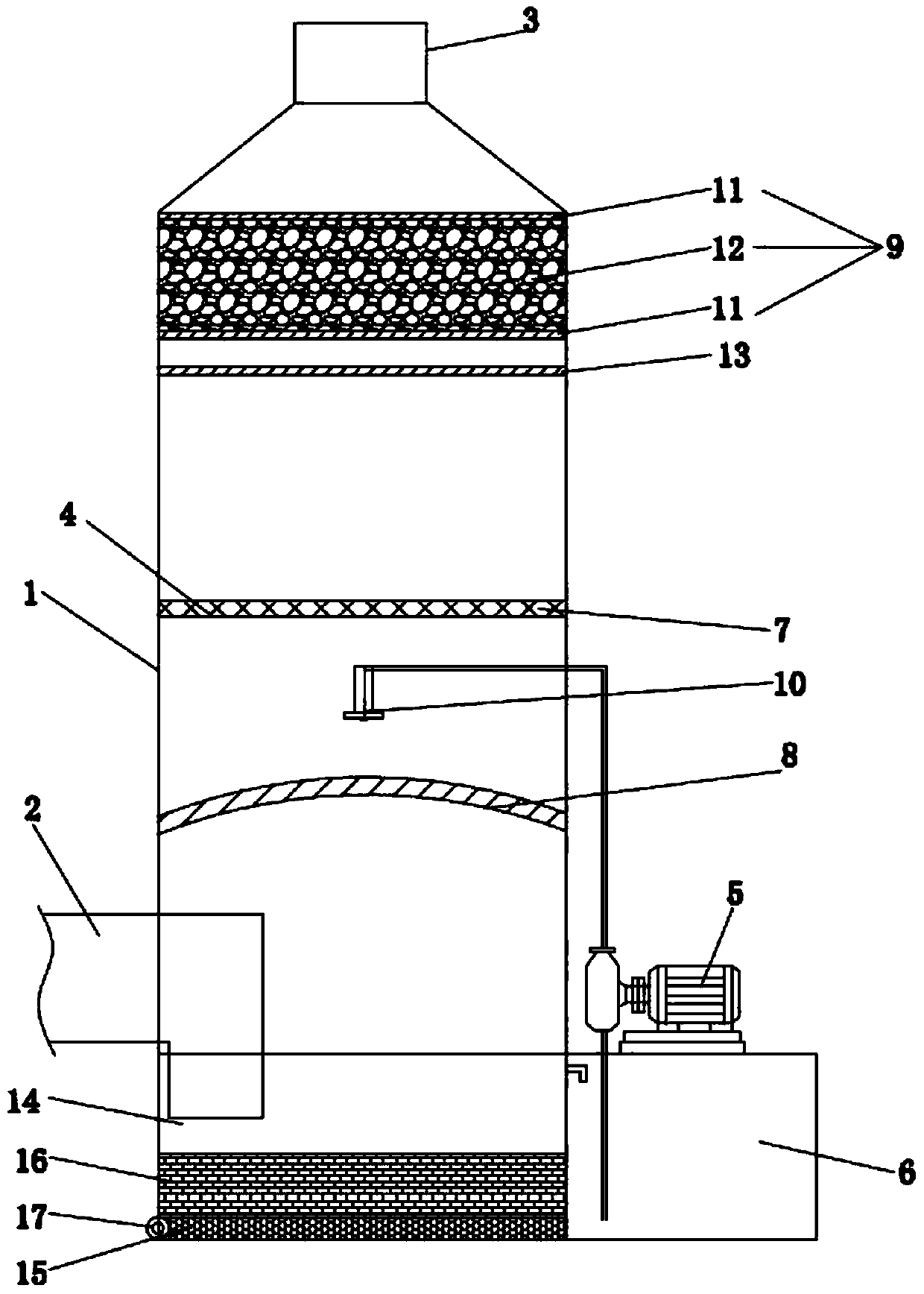
[0021] Such as figure 1 As shown, in order to achieve the above object described in the embodiment of the present invention, the present invention provides the following technical solutions: an exhaust gas treatment system, including a tower body 1, an air inlet 2, an air outlet 3, a filter device 4, a water pump assembly 5 and Reservoir 6, the air inlet 2 is located at the lower end of the tower body 1, the air outlet 3 is located at the top of the tower body 1, and the filter device 4 is arranged in the tower body 1 between the air inlet 2 and the air outlet 3 Between, the reservoir 6 is located on one side of the tower body 1, the reservoir 6 is connected to the tower body 1 through the water pump assembly 5, the filter device 4 includes a filter screen 7, a deflector 8 and an adsorption layer 9, The adsorption layer 9 is arranged at the upper end of the tower body 1, the filter screen 7 is arranged at the middle section of the tower body 1, and the deflector 8 is arranged ...


PUM


Abstract

The invention relates to an exhaust gas treatment system. The system comprises a tower, a gas inlet, a gas outlet, a filter device, a water pump assembly and a water storage tank, wherein the gas inlet is located in the lower end of the tower, the gas outlet is located in the top end of the tower, the filtering device is arranged in the tower and located between the gas inlet and the gas outlet, and the water storage tank is located on one side of the tower and connected with the tower through the water pump assembly; the filter device comprises a filter screen, a guide plate and an adsorptionlayer, the adsorption layer is arranged at the upper end of the tower, the filter screen is arranged at the middle section of the tower, and the guide plate is arranged below the filter screen; a nozzle assembly is arranged between the filter screen and the guide plate, and is connected with the water pump assembly. The system is simple in structure, can effectively remove particulate matter andwater vapor in exhaust gas, and does not cause blockage to a water pump. Meanwhile, harmful gas and gas carrying particulate matter can be filtered to the greatest extent by the arrangement of the filter screen, the guide plate and the nozzle assembly, and the filter effect is improved.

Description

technical field [0001] The invention belongs to the technical field of waste gas, in particular to a waste gas treatment system. Background technique [0002] At present, the existing method of spraying exhaust gas is relatively simple in structure. The tower body is provided with an air inlet and an air outlet, and a spray device is installed in the tower body. The exhaust gas enters the tower body from the air inlet and passes through the spray device. After spraying, it is discharged from the air outlet. After the exhaust gas is treated in this way, although the particulate matter in the exhaust gas can be filtered out, the exhaust gas contains water vapor, and the exhaust gas mixed with water vapor will also pollute the atmosphere, which is not conducive to environmental protection; In addition, the traditional tower is generally equipped with a water pump, and the water pump circulates the water at the bottom of the tower for spraying, but the recycled water contains pa...

Claims


Application Information

Patent Timeline
IPC IPC(8): B01D53/18B01D53/02B01D50/00
CPCB01D53/02B01D53/18B01D2252/103B01D50/60
Inventor 缪宜霖
Owner 缪宜霖
Why Eureka
Try Eureka