
Novel new energy vehicle energy charging method and realizing device thereof

A new energy vehicle and energy technology, applied in the direction of vehicle energy storage, control devices, vehicle components, etc., can solve the problems of reducing the use efficiency of new energy vehicles, limiting the promotion and use of new energy vehicles, and the difficulty of long-distance driving of new energy vehicles. Reduce energy replenishment time, improve sustainable driving ability, and reduce cost

Inactive Publication Date: 2018-05-11
上海尔行信息科技有限公司
View PDF6 Cites 8 Cited by
  • Summary
  • Abstract
  • Description
  • Claims
  • Application Information

AI Technical Summary

Problems solved by technology

[0002] At present, the basic structure of known new energy vehicle charging piles is composed of a base, a circuit, and a charging interface. Some charging piles have added Internet software to realize remote settlement and information query functions, but as far as the charging pile itself is concerned, not only one The charging pile can only correspond to 1-2 charging ports, and it still needs to stop the vehicle for a long time to recharge the battery, which greatly reduces the efficiency of new energy vehicles; and the power battery of new energy vehicles is limited by technology , the driving distance of the vehicle is limited, which makes it difficult for the new energy vehicles currently used in the market to travel long distances; the existing solution is only to increase the construction of charging piles, and realize the long-distance driving of new energy vehicles by increasing the distribution density of charging piles, but this This method is still limited by the time limit of recharging, and its practical value is not high, so that the long-distance driving of new energy vehicles cannot be truly realized, and thus limits the promotion and use of new energy vehicles

Method used


Image

  • Novel new energy vehicle energy charging method and realizing device thereof
  • Novel new energy vehicle energy charging method and realizing device thereof
  • Novel new energy vehicle energy charging method and realizing device thereof

Examples


Embodiment Construction

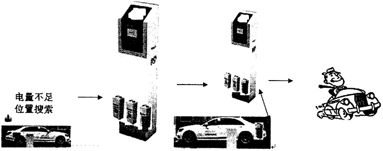
[0023] 1. in figure 1 Shown is an example of the overall system implementation of the method (solution) of the present invention. When the battery 8 in the new energy vehicle is running low, the battery status detector 4 sends a prompt message, and the user can use the background system to accurately locate the facility. Search and select a suitable battery replacement location; after arriving at the battery replacement location, take out the battery 8 with insufficient power in the car, and replace the battery 8 from the facilities described in the present invention according to the usage requirements, so as to realize the new energy vehicle in a short time Supplement the energy and continue driving.

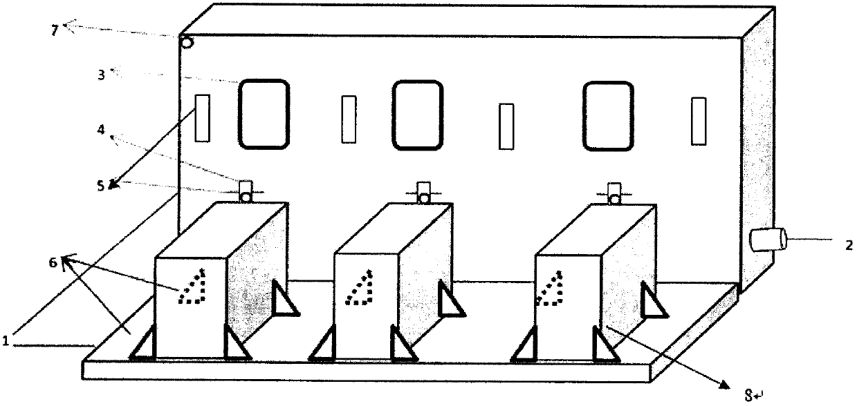
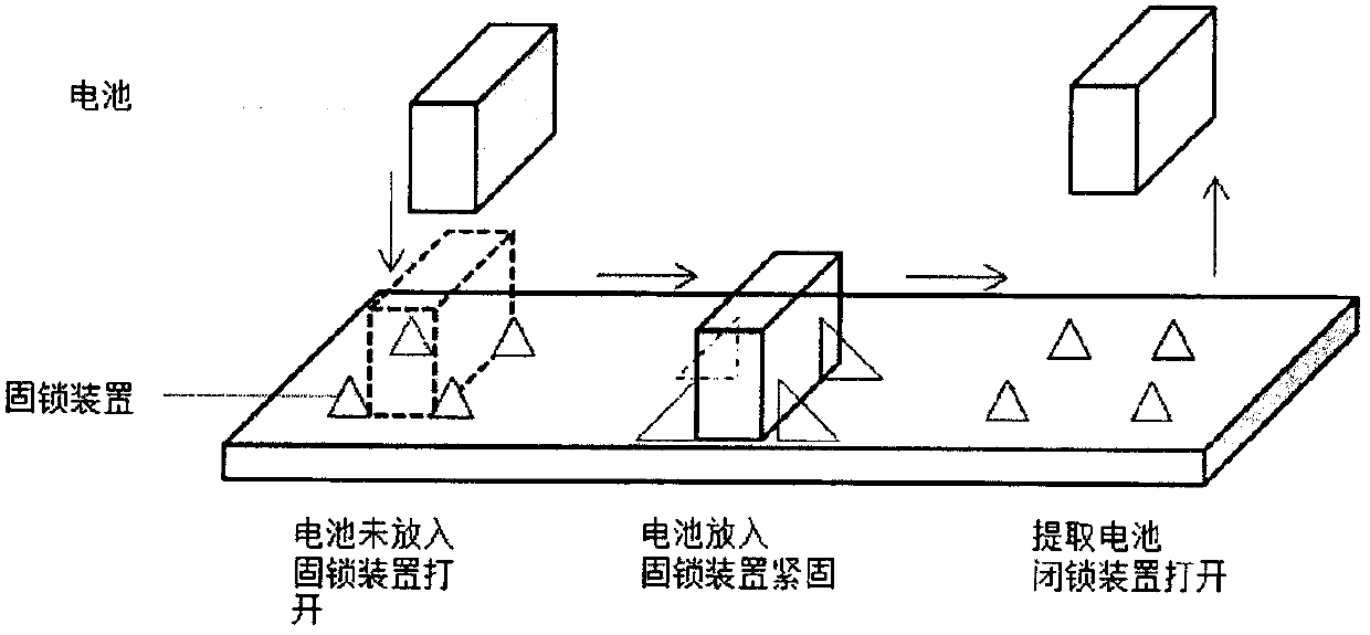
[0024] 2. The specific implementation device schematic diagram of the present invention is as figure 2 As shown, a battery locking device 6 is arranged on the charging pile base 1, and the battery is automatically detected for the new energy vehicle power battery 8 placed wit...


PUM


Abstract

The invention discloses a novel new energy vehicle power (energy) charging method. The power (energy) of a new energy vehicle is rapidly charged through power battery replacement. The novel new energyvehicle power (energy) charging method is specifically realized by using a novel multifunctional charging pile system. The novel multifunctional charging pile system; a charging pile comprises a base, a circuit, a display screen, a battery state detector, a charging interface, a fixedly locking device, a monitoring and alarming device and assorted control software. The novel multifunctional charging pile system is characterized in that the traditional charging function can be provided to the new energy vehicle having a charging requirement, new energy batteries with the same types can be shared by using the assorted control software technology, information technology and internet technology; the existing energy charging mode of the new energy vehicle is improved so that the vehicle power(energy) charging time is greatly saved and the bottleneck of restricting long-distance running of the new energy vehicle is solved.

Description

technical field [0001] The present invention relates to a method for quickly charging energy for new energy vehicles and its implementation device, especially for shared use of power batteries for new energy vehicles of the same type, which belongs to the high-tech field supported by the state——6. Energy and energy saving (3) New high-efficiency energy conversion and storage technology 2. Battery management system technology in new power battery (group) and energy storage battery technology. Background technique [0002] At present, the basic structure of known new energy vehicle charging piles is composed of a base, a circuit, and a charging interface. Some charging piles have added Internet software to realize remote settlement and information query functions, but as far as the charging pile itself is concerned, not only one The charging pile can only correspond to 1-2 charging ports, and it still needs to stop the vehicle for a long time to recharge the battery, which gre...

Claims


Application Information

Patent Timeline
IPC IPC(8): B60L11/18
CPCB60L2240/72B60L53/16B60L53/30B60L53/31B60L53/60B60L53/665B60L53/80B60L58/10Y02T10/70Y02T10/7072Y02T90/12Y02T90/14
Inventor 不公告发明人
Owner 上海尔行信息科技有限公司
Learn More