Permanent-magnet-spherical-motor position detection method based on 3-D magnetic-field sensors

A magnetic field sensor and detection method technology, applied in electromagnetic measurement devices, point coordinate measurement, complex mathematical operations, etc., can solve problems such as high working environment requirements, high position detection costs, and magnetic field models ignoring harmonics, and achieve anti-interference ability. Strong, small package, low cost effect

Inactive Publication Date: 2018-05-11
TIANJIN UNIV
View PDF5 Cites 7 Cited by
  • Summary
  • Abstract
  • Description
  • Claims
  • Application Information

AI Technical Summary

Problems solved by technology

Among the non-contact position detection methods, there are mainly position detection methods based on vision, optical sensors, and laser interferometers. However, the first two detection methods have high requirements for the working environment and are susceptible to external interference. The cost of position detection based on laser interferometers The magnetic field detection method has the advantages of strong anti-interference ability, unaffected by the working environment, high sensitivity, and small package, so it is favored by researchers. However, due to the complexity of the structure of the spherical motor, in order to simplify the calculation of the magnetic field model, it is often ignored. In addition, the complexity of the relationship between the output of the magnetic field sensor and the relationship between the rotor position hinders the widespread use of the magnetic field sensor

Method used


Image

  • Permanent-magnet-spherical-motor position detection method based on 3-D magnetic-field sensors
  • Permanent-magnet-spherical-motor position detection method based on 3-D magnetic-field sensors
  • Permanent-magnet-spherical-motor position detection method based on 3-D magnetic-field sensors

Examples


Embodiment Construction

[0044] The present invention will be described in further detail below in conjunction with the accompanying drawings and embodiments.

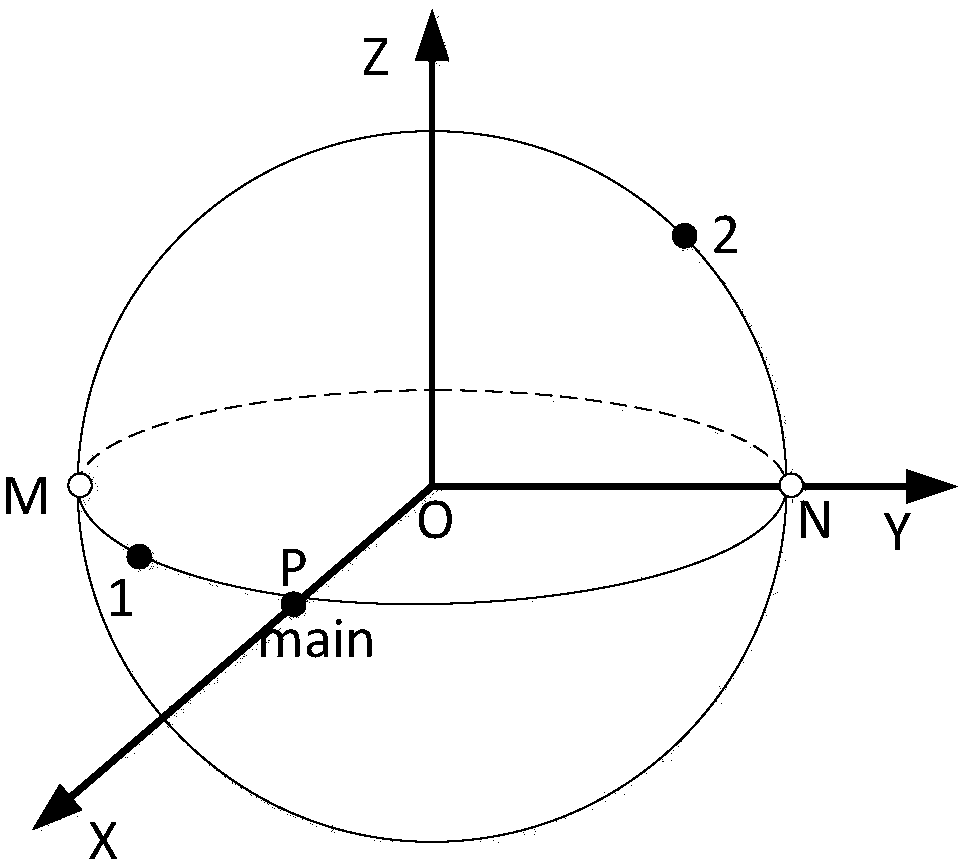
[0045] The present invention is a position detection algorithm proposed for the Halbach array permanent magnet spherical motor. In order to avoid the influence of rotor magnetic field harmonics, stator coil magnetic field and other interference on position detection, it realizes the work in the rotor through a magnetic field sensor combination scheme. Full coverage of the space, using a position calculation algorithm that combines the particle swarm algorithm and the gradient projection method for position calculation, can quickly and accurately obtain the position information of the rotor.

[0046] 1. Position detection model and main sensor magnetic field model

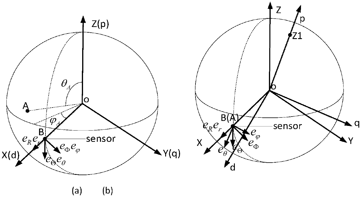
[0047] In order to study the magnetic field distribution of the spherical motor rotor and describe the motion of the rotor, the stator rectangular coordinate system Σ(XYZ), the stat...


PUM


Abstract

The invention relates to a permanent-magnet-spherical-motor position detection method based on 3-D magnetic-field sensors. A motor in which the method is suitable for use is a permanent-magnet spherical-motor, which includes a base, a spherical stator, stator coils and a spherical rotor. The rotor is located in a stator wall, and a rotor output shaft thereof extends out of an opening place on thestator wall. The motor is characterized in that the stator coils are cylindrical coreless structures, and three layers thereof are evenly distributed along an equator inside the spherical stator and on coils which are parallel to the equator, and are radially fixed on the spherical stator wall; and permanent-magnet poles are embedded in a surface of the rotor, the poles are divided into an upper layer and a lower layer along the equator, and N poles and S poles of each layer are alternately distributed. The position detection method includes: firstly, obtaining nonlinear relationships betweenmagnetic induction intensity and rotor position information according to a magnetic-field model and rotation transformation theory; integrating all the magnetic-field sensors to determine a fitness function of position calculation; and utilizing a position calculation algorithm, which combines a particle swarm algorithm and a gradient projection method, to carry out position resolution to obtain position information of the rotor.

Description

technical field [0001] The invention belongs to the technical field of position detection of a permanent magnet spherical motor, and relates to a position detection method of a permanent magnet spherical motor based on a 3-D magnetic field sensor. Background technique [0002] Multi-degree-of-freedom manipulators are widely used. In modern aerospace, military, industrial automation, intelligent robots and other fields, it is required that the end effector of multi-degree-of-freedom manipulators can be adjusted quickly, smoothly and accurately. To complete the multi-degree-of-freedom movement of the current device, it needs the mutual cooperation of multiple single-degree-of-freedom driving elements and complex mechanical transmissions. In this way, not only will the system be complicated, but also the loss of the system will be increased and the dynamic performance of the system will be reduced. These factors have promoted the development of spherical motors that can indepe...

Claims


Application Information

Patent Timeline
Patent Type & Authority Applications(China)
IPC IPC(8): G06F17/12G06F17/15G01B7/004
CPCG01B7/004G06F17/12G06F17/15
Inventor 李洪凤柳文俊
Owner TIANJIN UNIV
Why Eureka
Try Eureka