
Polishing equipment
A kind of equipment, one-sided technology, applied in the field of polishing equipment, can solve problems such as trouble, grinding debris residue, safety hazards, etc., to achieve the effect of improving safety performance and speeding up grinding efficiency
- Summary
- Abstract
- Description
- Claims
- Application Information
AI Technical Summary
Problems solved by technology
Method used
Image

Examples
Embodiment Construction
[0022] The present invention will be described in further detail below by means of specific embodiments:
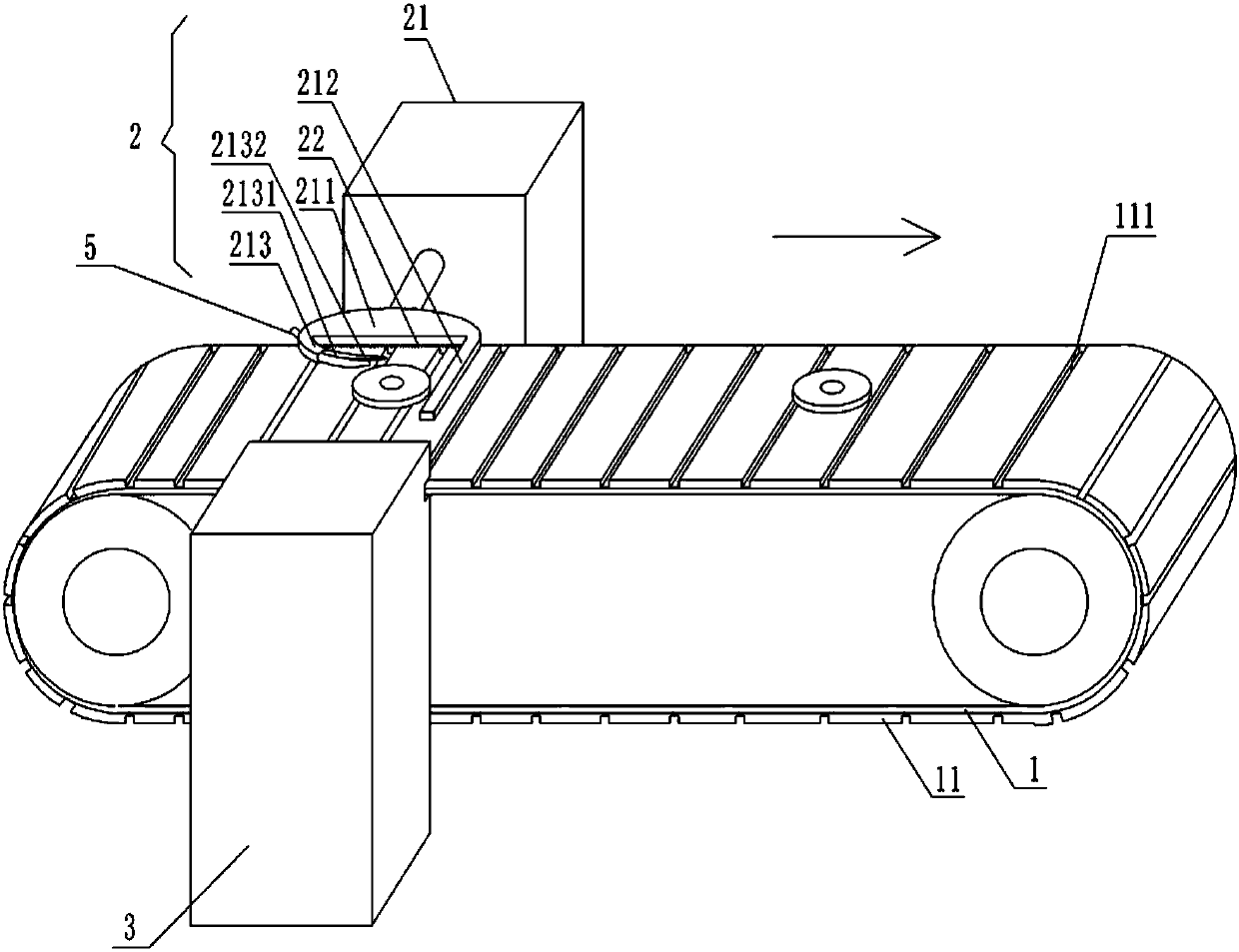
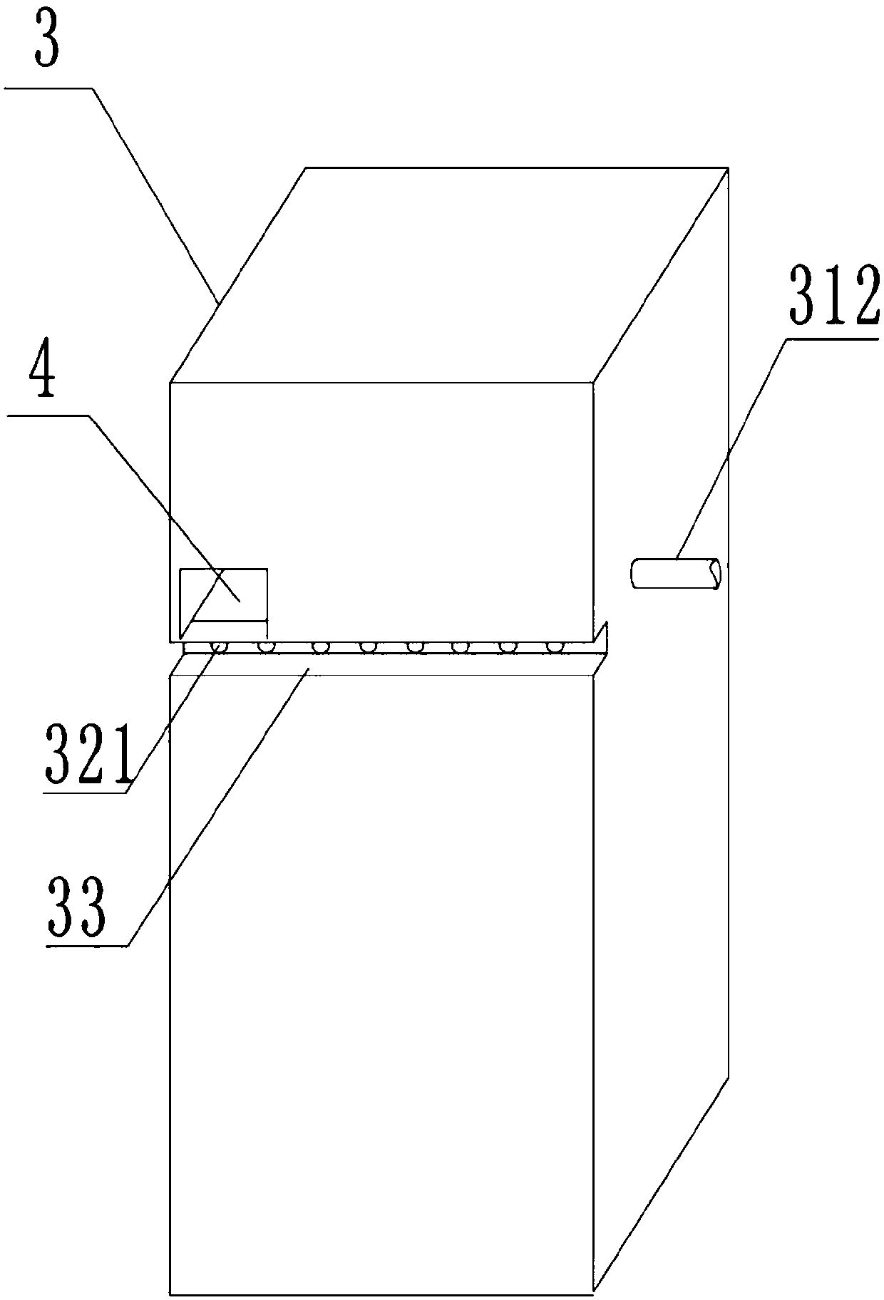
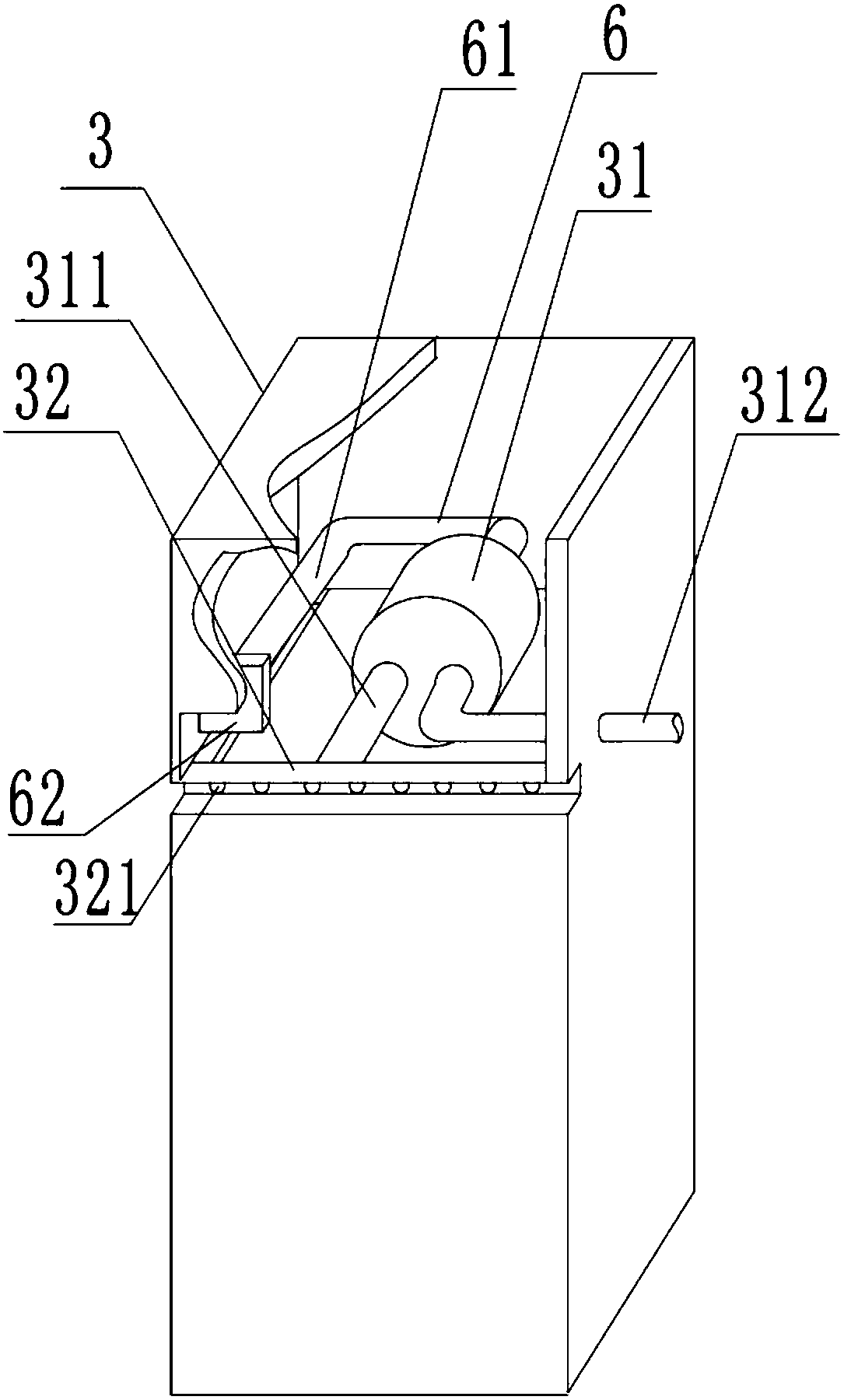
[0023] The reference signs in the accompanying drawings of the description include: the conveying surface 1, the grinding layer 11, the dust collection tank 111, the grinding part 2, the fixed table 21, the cleaning brush 22, the plate body 211, the stop rod 212, the arc-shaped outer cover 213, the arc-shaped Limiting block 2131, baffle plate 2132, fixed body 3, dust suction cylinder 31, dust suction pipe 311, dust discharge pipe 312, strip box 32, chip suction hole 321, chute 33, insertion port 4, threaded rod 5, L-shaped bar 6, connecting rod 61, pushing block 62.
[0024] In order to achieve the above object, the basic scheme of the present invention is as follows:
[0025] Such as figure 1 As shown, a polishing device includes a conveyor belt, a polishing part 2, a dust suction part and a motor for driving the conveyor belt to move to the right; the dust suction par...
PUM
 Abstract
Description
Claims
Application Information