Synchronous heat treatment device for on-line producing crankshafts

A heat treatment device and crankshaft technology, applied in heat treatment furnaces, heat treatment equipment, furnace types, etc., can solve the problems of not being able to use a crankshaft production line, increase crankshaft deformation, and high heat treatment costs, and achieve the effects of small deformation, uniform heating and low cost.

Pending Publication Date: 2018-05-15
HUBEI UNIV OF AUTOMOTIVE TECH
View PDF3 Cites 0 Cited by
  • Summary
  • Abstract
  • Description
  • Claims
  • Application Information

AI Technical Summary

Problems solved by technology

[0003] The heat treatment of crankshaft journal and fillet mainly has two methods: on-line production heat treatment and off-line heat treatment: for now, in the process of on-line production heat treatment, the crankshaft is placed horizontally without auxiliary support in the middle, and tempering heat correction is required during the heat treatment process. Straight process, heat transfer and crankshaft self-weight will increase crankshaft deformation; off-line heat treatment usually adopts stacking, tiling or hanging centralized heat treatment method, which requires a special heat treatment production line, which cannot be used with the crankshaft production line. During heat treatment, the crankshaft is stationary. There are many disadvantages such as uneven heating, large deformation, high cost of heat treatment, slow production cycle, etc.

Method used


Image

  • Synchronous heat treatment device for on-line producing crankshafts
  • Synchronous heat treatment device for on-line producing crankshafts
  • Synchronous heat treatment device for on-line producing crankshafts

Examples


Embodiment

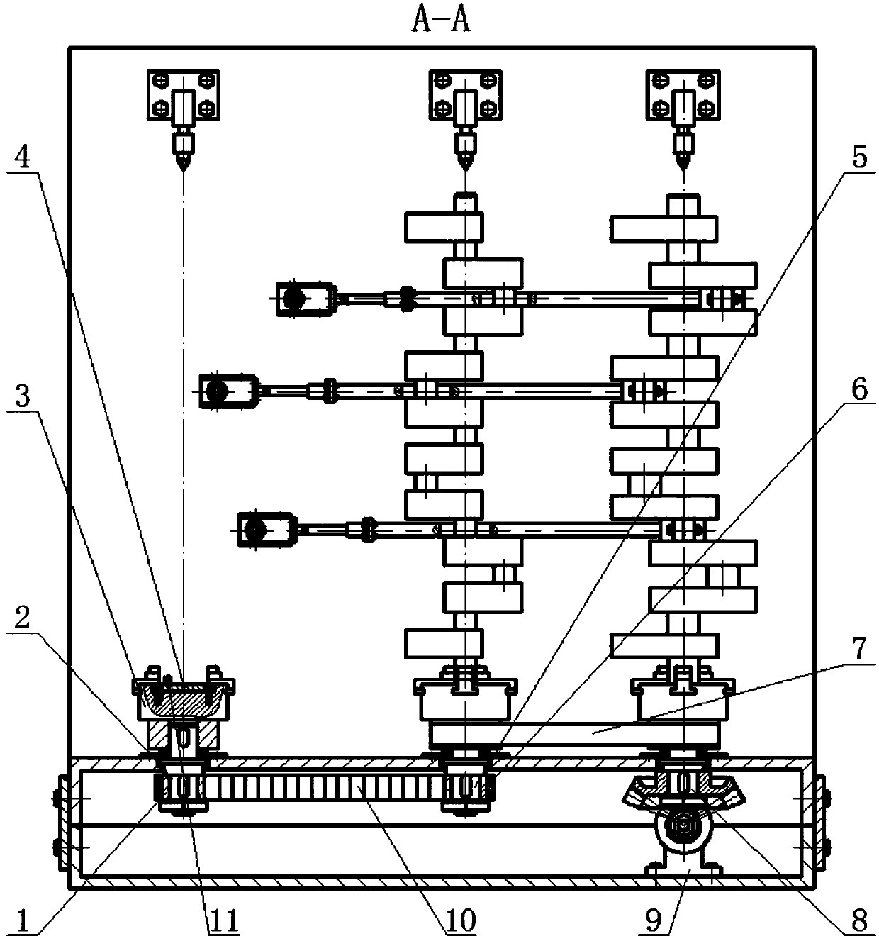
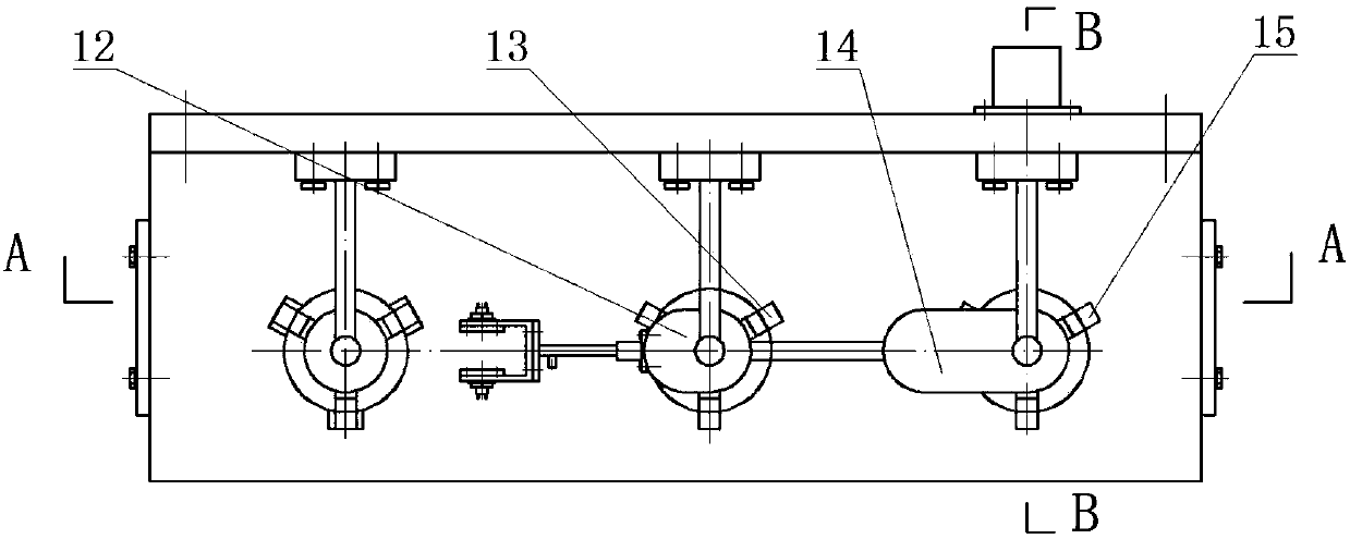
[0033] The workflow of a kind of on-line crankshaft synchronous heat treatment device provided by the present invention is as follows:

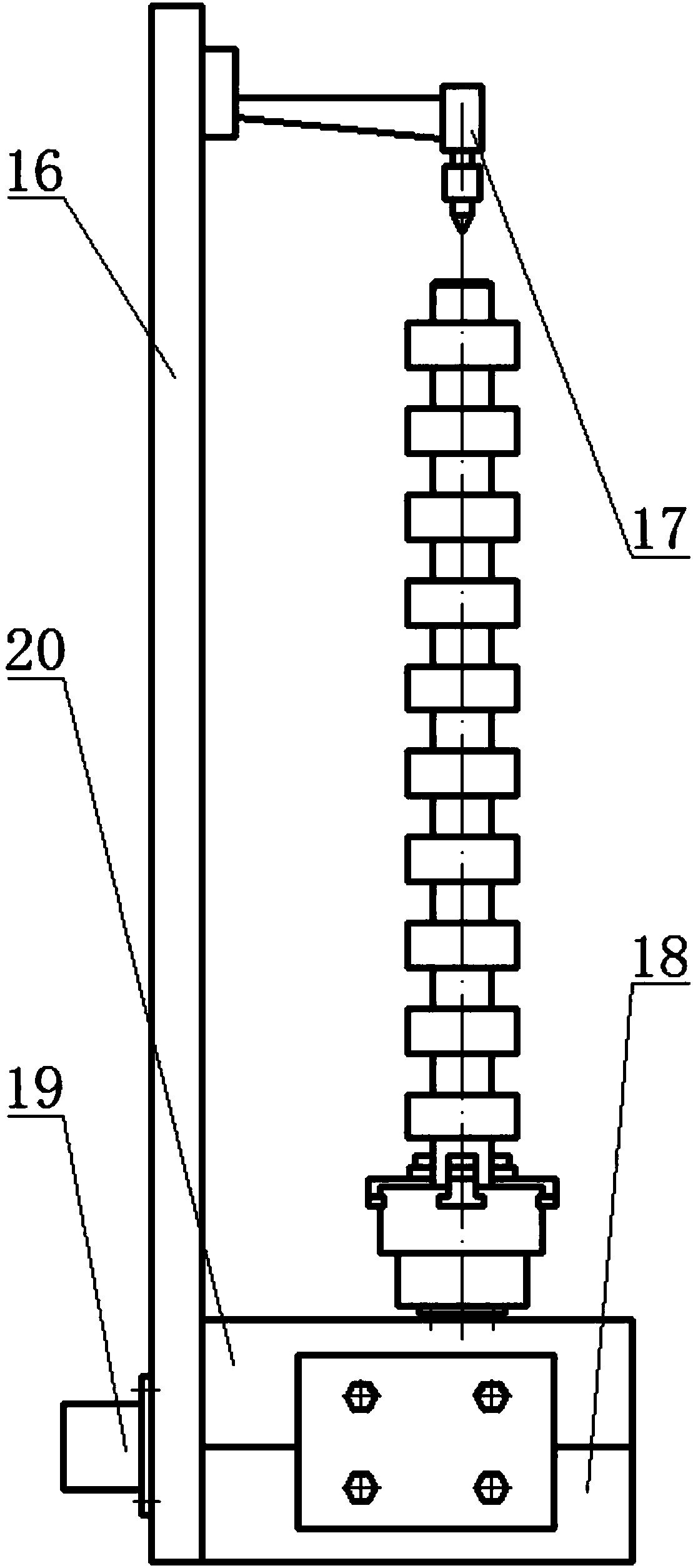
[0034] During the heat treatment of the crankshaft, the crankshaft is positioned and clamped by the positioning and clamping mechanism, the parallelogram mechanism and the crankshaft are driven by the synchronous transmission mechanism to rotate synchronously, and the parallelogram mechanism drives the induction heating mechanism to move in translation in the horizontal plane to ensure that the induction heater is in contact with the crankshaft shaft. The relative position of the neck remains unchanged, and it does not contact the crankshaft journal to prevent scratching the crankshaft journal. The crankshaft is heated and heat-insulated by the induction heating mechanism. The specific process includes:

[0035] The positioning and clamping mechanism realizes the positioning and clamping of the crankshaft: the crankshaft is mainly positioned ...


PUM


Abstract

The invention discloses a synchronous heat treatment device for on-line producing crankshafts. The synchronous heat treatment device for on-line producing the crankshafts comprises a positioning and clamping mechanism, a synchronous transmission mechanism, a parallelogram mechanism and an induction heating mechanism. The positioning and clamping mechanism is used for positioning and clamping the produced crankshafts; the synchronous transmission mechanism is used for driving the parallelogram mechanism and the crankshafts to rotate; the parallelogram mechanism is used for driving the inductionheating mechanism to move transversely in a horizontal plane; and the induction heating mechanism is used for heating and carrying out heat-insulation heat treatment on the crankshafts. When the device carries out heat treatment, the crankshafts are vertically placed, a heat treatment part is heat uniformly so as to be less in deformation, the heat treatment efficiency is high, and the device canbe suitable for on-line heat-treating multi-species crankshafts.

Description

technical field [0001] The invention belongs to the technical field of metal surface heat treatment, and relates to a heat treatment device for an automobile crankshaft, in particular to a synchronous heat treatment device for an online production crankshaft. Background technique [0002] The crankshaft is an important component of the automobile engine. Its production quality, especially the stress concentration, fatigue cracks or fractures at the crankshaft journal and fillets, have a great impact on the service life and comprehensive performance of the engine. To eliminate such effects, crankshafts are usually heat treated during production. [0003] The heat treatment of crankshaft journal and fillet mainly has two methods: on-line production heat treatment and off-line heat treatment: for now, in the process of on-line production heat treatment, the crankshaft is placed horizontally without auxiliary support in the middle, and tempering heat correction is required durin...

Claims


Application Information

Patent Timeline
Patent Type & Authority Applications(China)
IPC IPC(8): C21D9/30C21D1/42
CPCC21D1/42C21D9/0025C21D9/30Y02P10/25
Inventor 李然王宸陈君宝袁海兵
Owner HUBEI UNIV OF AUTOMOTIVE TECH
Why Eureka
Try Eureka