Novel concrete base safety guard device

A technology of safety guardrail and concrete base, which is applied to road safety devices, roads, roads, etc., can solve problems such as the inability to meet the needs of road maintenance, and achieve the effects of reducing operation time, simple production and low cost.

Pending Publication Date: 2018-05-15
张玉建
View PDF0 Cites 3 Cited by
  • Summary
  • Abstract
  • Description
  • Claims
  • Application Information

AI Technical Summary

Problems solved by technology

[0007] Therefore, the commonly used methods of directly driving piles and extracting piles and existing replaceable guardrails connected by flanges and bolts can no longer meet the needs of road maintenance on accident-prone sections in western mountainous areas. , At the same time, it can be well compatible with the current standard facilities, and it is a low-cost road safety protection device

Method used


Image

  • Novel concrete base safety guard device
  • Novel concrete base safety guard device
  • Novel concrete base safety guard device

Examples


Embodiment 1

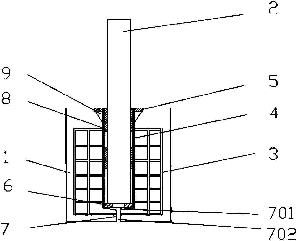
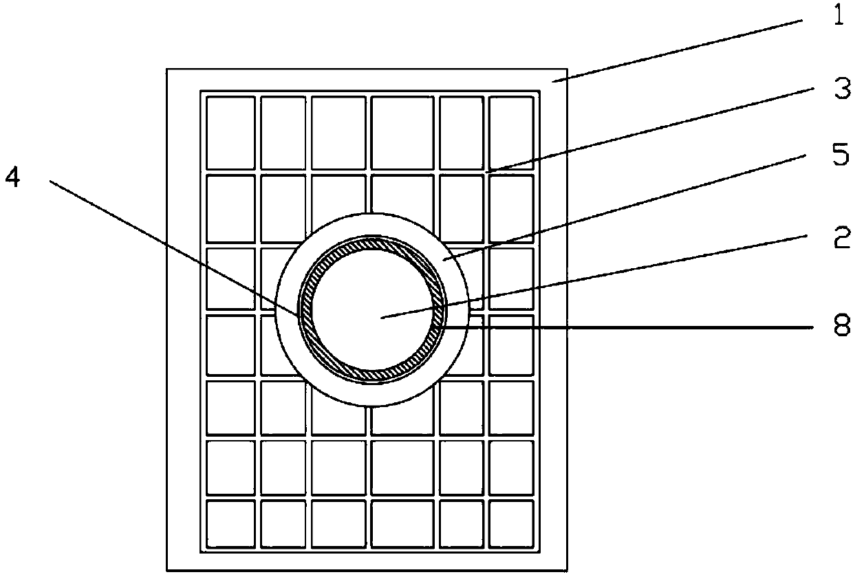
[0049] combined with Figure 1-3 , a new type of concrete base safety guardrail device, including a base 1 and a column 2 arranged in the base 1, the base 1 is made of concrete cast-in-place or factory prefabricated, and the base 1 is integrated with the roadbed One;

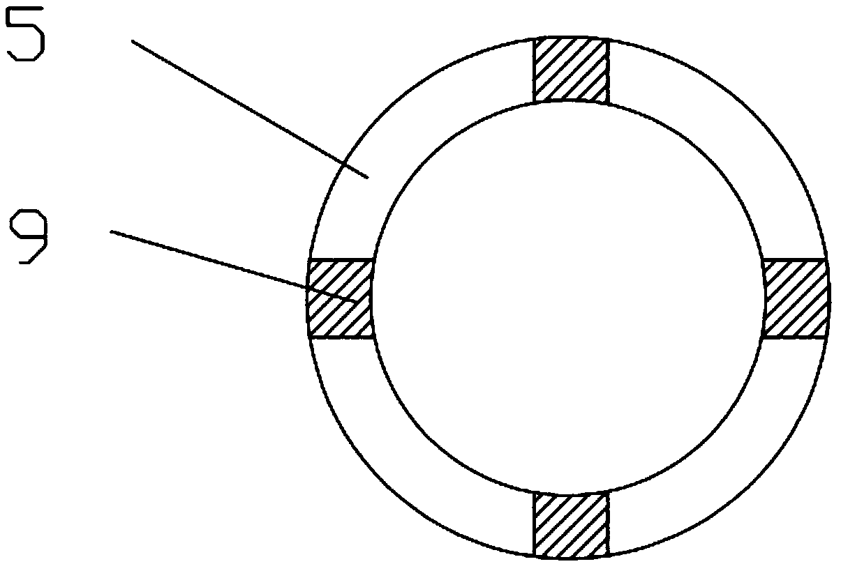
[0050] A reinforcing cage 3 is pre-embedded in the base 1, and a column cavity is provided in the base 1, and a column cover 4 is preset on the inner side of the column cavity, and the column cover 4 is fixedly connected with the reinforcing cage 3, The outer ring of the upper edge of the column cover 4 is fixedly connected with a reinforcing plate 5, and the lower edge is provided with a drainage channel 7 downward, and several limit blocks 6 are fixedly connected to the inner wall of the column cover 4;

[0051] Between the inner wall of the column cover 4 and the column 2, several shock-absorbing blocking parts 8 are arranged from top to bottom.

[0052] As a preferred implementation of this embodiment, one...

Embodiment 2

[0069] combined with Figure 3-5 , a new type of concrete base safety guardrail device, including a base 1 and a column 2 arranged in the base 1, the base 1 is made of concrete cast-in-place or factory prefabricated, and the base 1 is integrated with the roadbed One;

[0070] A reinforcing cage 3 is pre-embedded in the base 1, and a column cavity is provided in the base 1, and a column cover 4 is preset on the inner side of the column cavity, and the column cover 4 is fixedly connected with the reinforcing cage 3, The outer ring of the upper edge of the column cover 4 is fixedly connected with a reinforcing plate 5, and the lower edge is provided with a drainage channel 7 downward, and several limit blocks 6 are fixedly connected to the inner wall of the column cover 4;

[0071] Between the inner wall of the column cover 4 and the column 2, several shock-absorbing blocking parts 8 are arranged from top to bottom.

[0072] As a preferred implementation of this embodiment, one...


PUM


Abstract

The invention discloses a novel concrete base safety guard device, comprising a base and a vertical post arranged in the base; the base is made of cast-in-place concrete or pre-made in a factory; thebase is integrated to a subgrade; a reinforcing cage is embedded in the base; a post cavity is arranged in the base; a post sleeve is pre-arranged on the inner periphery of the post cavity and is fixedly connected with the reinforcing cage; the upper peripheral rig of the post sleeve is fixedly connected with a reinforcing disc, the lower peripheral edge of the post sleeve is provided with a drainpassage, a plurality of limiting blocks are fixed to the inner wall of the post sleeve, and a plurality of damping seal rings are arranged between the inner wall of the post sleeve and the vertical post from top to bottom. The novel concrete base safety guard device has the advantages that the damaged vertical post is quick to change so that operating time is effectively shortened for construction staff; the novel concrete base safety guard device is well compatible with current standard facilities and is highly applicable; materials selected herein are common, the novel concrete base safetyguard device is simple to manufacture and widely applicable, and the vertical post in a vertical tube can be protected from damage so that reusing is achieved; the novel concrete base safety guard device is solid, durable, economical and reliable, and low in cost.

Description

technical field [0001] The invention relates to the field of highway safety protection, in particular to a novel concrete base safety guardrail device. Background technique [0002] At present, my country's highway safety guardrail generally adopts steel column and wave beam structure, which greatly improves the protection level and reduces the occurrence of accidents. It is very practical in areas with less accidents and less maintenance, but in the vast Midwest, especially in mountainous areas, where sharp bends and downhill roads are the most common and accident-prone, this process is still used for the construction and maintenance of guardrails. It is far from meeting the actual needs. [0003] If the column encounters hard pebbles and rock formations when it is driven in, the middle and lower part of the column will be skewed, trumpet-shaped and torn and twisted, like a big tree root. The soil and rocks are carried out and loosened, which not only increases the difficul...

Claims


Application Information

Patent Timeline
Patent Type & Authority Applications(China)
IPC IPC(8): E01F15/04
CPCE01F15/0461E01F15/0469E01F15/0476
Inventor 张玉建
Owner 张玉建
Why Eureka
Try Eureka