Turbocharging electric control bypass valve design

A turbocharger and turbocharger technology, applied in valve details, valve devices, mechanical equipment, etc., can solve problems such as vibration noise, reduced reliability life, system wear, etc., to reduce frequency, increase reliability and life. , the effect of reducing output torque and power requirements

Pending Publication Date: 2018-05-15
SUZHOU FUGENA ELECTROMECHANICAL CO LTD
View PDF3 Cites 1 Cited by
  • Summary
  • Abstract
  • Description
  • Claims
  • Application Information

AI Technical Summary

Problems solved by technology

[0006] The purpose of the present invention is to solve the problems of system wear, vibration noise, reliability

Method used


Image

  • Turbocharging electric control bypass valve design
  • Turbocharging electric control bypass valve design
  • Turbocharging electric control bypass valve design

Examples


Embodiment Construction

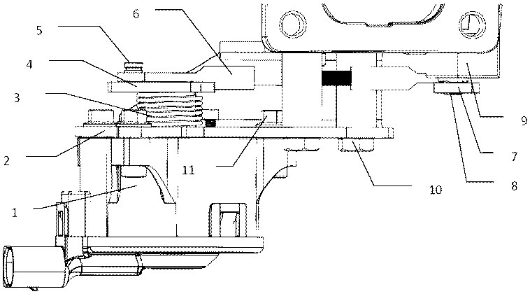
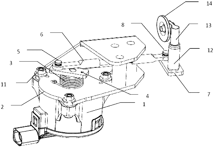
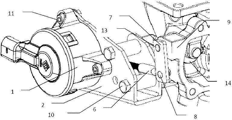
[0028] figure 1 It is a structural perspective view of a turbocharger bypass valve with a preloaded spring in a preferred embodiment of the present invention. This embodiment is as follows: the actuator installation and fixing plate 2 is fixed to the turbine casing 9 through a plurality of bolts 10 , and the brushless torque actuator 1 is fixed to the actuator installation and fixing plate 2 through a plurality of bolts 11 . The output shaft of the actuator is fixedly connected with the rocker arm 4 on the driving side. Fixed connection methods such as welding, riveting, etc. are usually used. A spring 3 is installed between the driving side rocker arm 4 and the actuator mounting plate 2 . The spring is preloaded by rotation before installation. The driving side rocker arm 4 is connected with the connecting rod 6 movable mechanism through the driving side pivot pin 5 . Its connection method can be common shaft pin, also can be various bearing sleeves, in order to reduce fr...


PUM


Abstract

The invention relates to a turbocharging electric control bypass valve structure design. The bypass valve structure comprises a bypass valve plate arranged on a turbocharger, an electric executer arranged on the turbocharger, a transmission mechanism connecting the electric executer with the bypass valve plate, and a spring generating pre-tightening force to the transmission mechanism. Due to thepre-tightening force generated through the spring, the bypass valve plate generates closing force. A brushless direct drive torque motor is preferably selected in the executer. By means of the turbocharging electric control bypass valve structure design, the mechanical gap of the bypass valve transmission mechanism can be effectively eliminated, and vibration abrasion, noise, lowering of reliability and shortening of the service life due to the gap are avoided. The executer torque and power requirements are lowered, and heat dissipation is reduced. Due to usage of the brushless direct drive torque motor, the reliability of the system can be greatly improved, and the service life of the system can be greatly prolonged.

Description

technical field [0001] The invention relates to the design of a turbocharger electronically controlled bypass valve. Background technique [0002] With the continuous tightening of regulations, the fuel consumption and emission requirements of engines are also getting higher and higher. Turbocharging has become a commonly used technical route for engines. Traditional turbocharger bypass valves are controlled mechanically or pneumatically, which has poor response and low control precision. According to the latest emission regulations, most engines need to adopt SCR exhaust gas treatment technology. The SCR needs to be above a certain temperature to start working. The traditional bypass valve cannot open the bypass valve under cold start low pressure conditions, resulting in a decrease in the temperature of the exhaust gas in the turbocharger module, further slowing down the heating of the SCR, and making it more difficult to achieve cold start emissions. In order to meet ...

Claims


Application Information

Patent Timeline
IPC IPC(8): F02B37/18F02B37/22F16K31/04
CPCF02B37/186F02B37/22F16K31/043Y02T10/12
Inventor 不公告发明人
Owner SUZHOU FUGENA ELECTROMECHANICAL CO LTD
Why Eureka
Try Eureka