
Feed drying device facilitating material discharge

A drying device and feed technology, applied in the direction of drying, drying machine, drying gas arrangement, etc., can solve the problems of high moisture content, low drying efficiency, death, etc., achieve high degree of automation, speed up drying, even drying effect

Inactive Publication Date: 2018-05-15
ZHENGZHOU LIFUAI BIOLOGICAL TECH CO LTD
View PDF5 Cites 6 Cited by
  • Summary
  • Abstract
  • Description
  • Claims
  • Application Information

AI Technical Summary

Problems solved by technology

[0002] In the ecological breeding process of poultry, it is necessary to put in pollution-free feed, the feed must be proportioned scientifically and the feeding needs to be precise, and the moisture of the raw materials in the feed must also be strictly controlled to avoid moldy feed; the moisture content of the granulated feed produced during the production process of the feed High, so the feed is prone to deterioration during storage and transportation, and the livestock will easily get sick or even die after eating the deteriorated feed, which seriously affects the economic income of the breeder
In order to store and transport the feed for a long time, it needs to be dried before the feed leaves the factory. The existing drying equipment has unreasonable structural design, uneven drying effect, low drying efficiency, and the feed is not dried after drying. It is time-consuming and labor-intensive to facilitate discharge; therefore, we need a feed drying device that is convenient for discharge

Method used


Image

  • Feed drying device facilitating material discharge
  • Feed drying device facilitating material discharge
  • Feed drying device facilitating material discharge

Examples


Embodiment Construction

[0016] The technical solution of this patent will be further described in detail below in conjunction with specific embodiments.

[0017] Embodiments of the present patent are described in detail below, examples of which are shown in the drawings, wherein the same or similar reference numerals designate the same or similar elements or elements having the same or similar functions throughout. The embodiments described below by referring to the figures are exemplary and are only used for explaining the patent, and should not be construed as limiting the patent.

[0018] In the description of this patent, it is to be understood that the terms "center", "upper", "lower", "front", "rear", "left", "right", "vertical", "horizontal", The orientation or positional relationship indicated by "top", "bottom", "inner", "outer", etc. is based on the orientation or positional relationship shown in the drawings, and is only for the convenience of describing this patent and simplifying the des...


PUM


Abstract

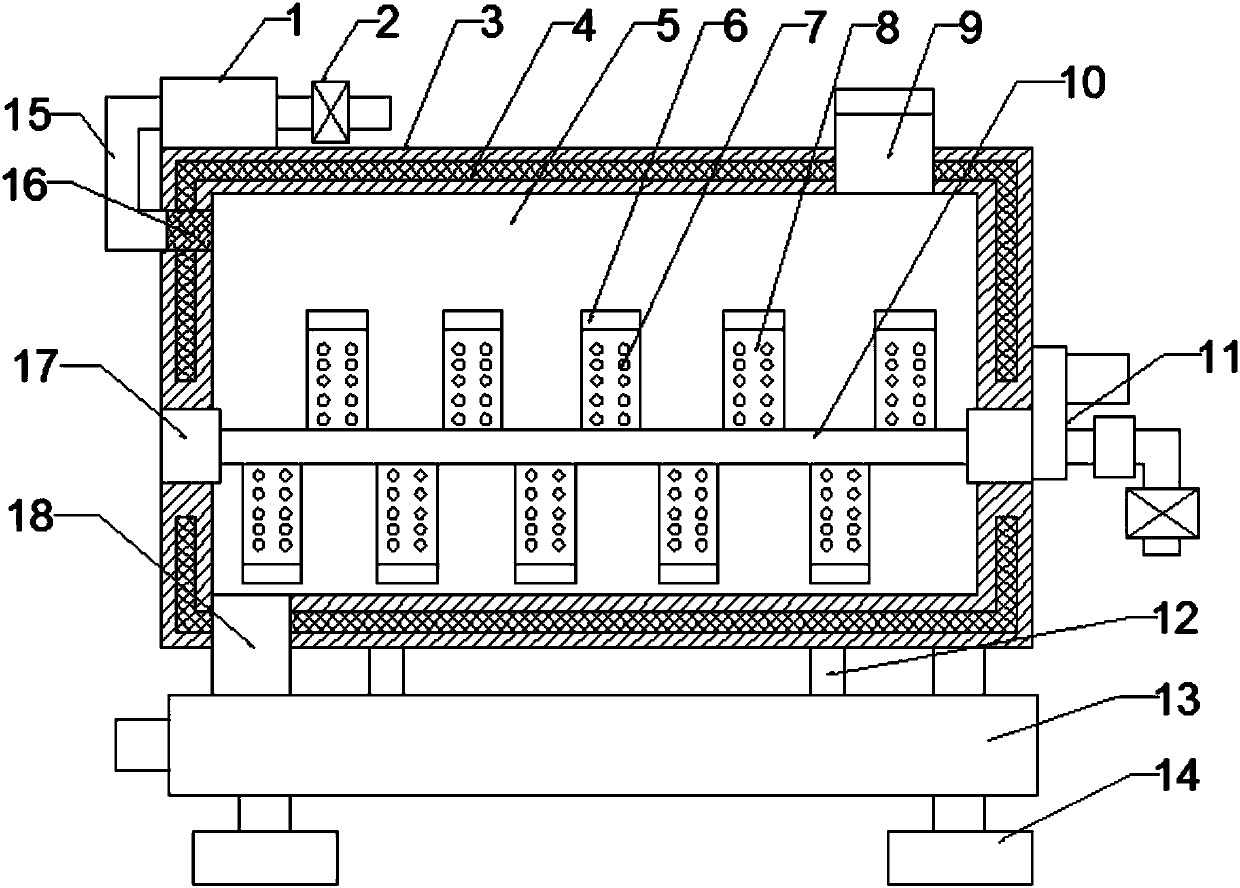
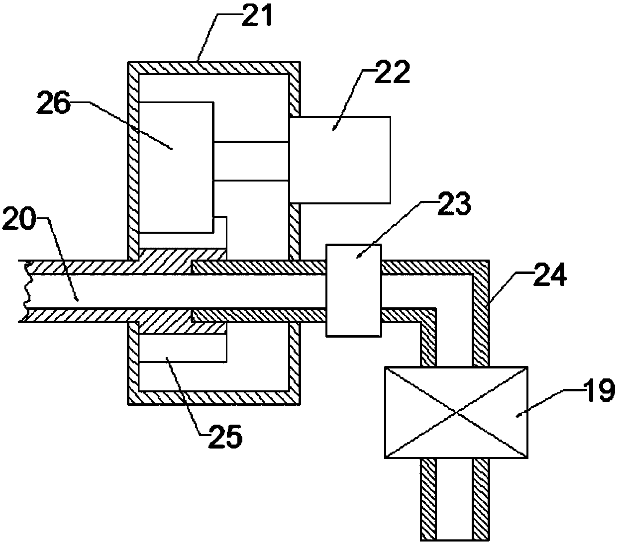
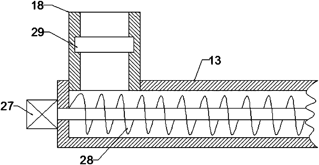
The invention discloses a feed drying device facilitating material discharge, and belongs to the technical field of feed processing. The feed drying device comprises a blending tank, a scrapper plate,stirring pieces, a feed tank, a stirring shaft, a driving and drying device, a material discharge pipe, support legs and a dehumidification pipe; the feed drying device is characterized in that the blending tank is a hollow cylinder arranged horizontally, and made of stainless steel materials; the inner wall of the blending tank is provided with a thermal insulation layer, and the blending tank is internally provided with a mixing chamber; the feed tank is arranged on the right side of the top end of the blending tank, and communicates with the mixing chamber; the stirring pieces are fixed tothe same cross section of the stirring shaft, and divided into an upper row and a lower row, and the two rows of the stirring pieces are staggered; and the surfaces of the stirring pieces are evenlyprovided with a plurality of blowholes, and the stirring pieces and the stirring shaft are internally provided with gas channels. The feed drying device disclosed by the invention is rational in structure and high in drying efficiency, and feed is stirred by a stirring device; and the feed adhering to the inner wall of the tank is scrapped by the scrapper plate, and the feed drying device is uniform in drying, and facilitates material discharge.

Description

technical field [0001] The invention relates to the technical field of feed processing, in particular to a feed drying device which is convenient for discharging. Background technique [0002] In the ecological breeding process of poultry, it is necessary to put in pollution-free feed, the feed must be proportioned scientifically and the feeding needs to be accurate, and the moisture of the raw materials in the feed must also be strictly controlled to avoid moldy feed; the moisture content of the pelleted feed produced during the feed production process High, so the feed is prone to deterioration during storage and transportation, and the livestock will easily get sick or even die after eating the deteriorated feed, which seriously affects the economic income of the breeder. In order to store and transport the feed for a long time, it needs to be dried before the feed leaves the factory. The existing drying equipment has unreasonable structural design, uneven drying effect, ...

Claims


Application Information

Patent Timeline
Patent Type & Authority Applications(China)
IPC IPC(8): F26B11/16F26B21/00F26B25/00F26B25/04
CPCF26B11/16F26B21/001F26B21/004F26B25/002F26B25/007F26B25/04
Inventor 张健健
Owner ZHENGZHOU LIFUAI BIOLOGICAL TECH CO LTD
Learn More