Structured light illumination-based fluorescent dipole orientation method

A technology of structured light illumination and dipole, which is applied in the field of super-resolution fluorescence microscopy, can solve the problems of image quality degradation, difficulty in obtaining, and total light intensity reduction, and achieves a highly popularized, low-cost and easy-to-implement Effect

Active Publication Date: 2018-05-15
北京艾锐精仪科技有限公司
View PDF9 Cites 1 Cited by
  • Summary
  • Abstract
  • Description
  • Claims
  • Application Information

AI Technical Summary

Problems solved by technology

Among the above three existing technologies, the first type requires high-magnification images, and the diffraction images of adjacent dipoles will overlap, making it difficult to obtain high spatial resolution. In addition, the accuracy of pattern comparison is limited by the signal-to-noise ratio. The impact is great; the second type is faster, but the beam splitter reduces the total light intensity obtained on each picture, thereby reducing the signal-to-noise ratio and image quality; the third type of system needs to collect multiple pictures and consumes longer time
In addition, the optical paths of the latter two types of technologies are relatively complex, which is not conducive to integration on commercial systems

Method used


Image

  • Structured light illumination-based fluorescent dipole orientation method
  • Structured light illumination-based fluorescent dipole orientation method
  • Structured light illumination-based fluorescent dipole orientation method

Examples


Embodiment Construction

[0023] The present invention will be described in detail below in conjunction with the accompanying drawings. However, it should be understood that the accompanying drawings are provided only for better understanding of the present invention, and they should not be construed as limiting the present invention.

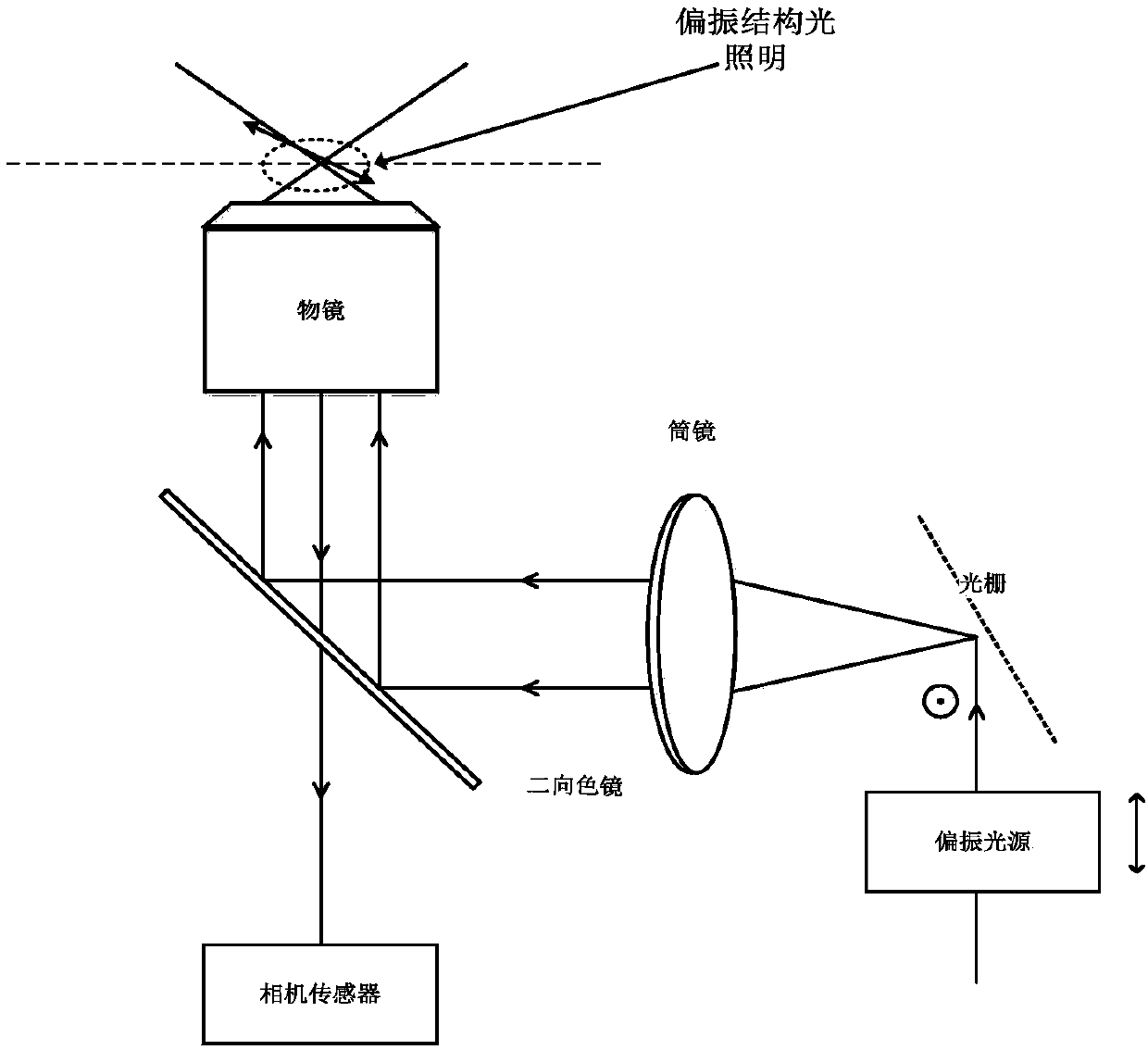
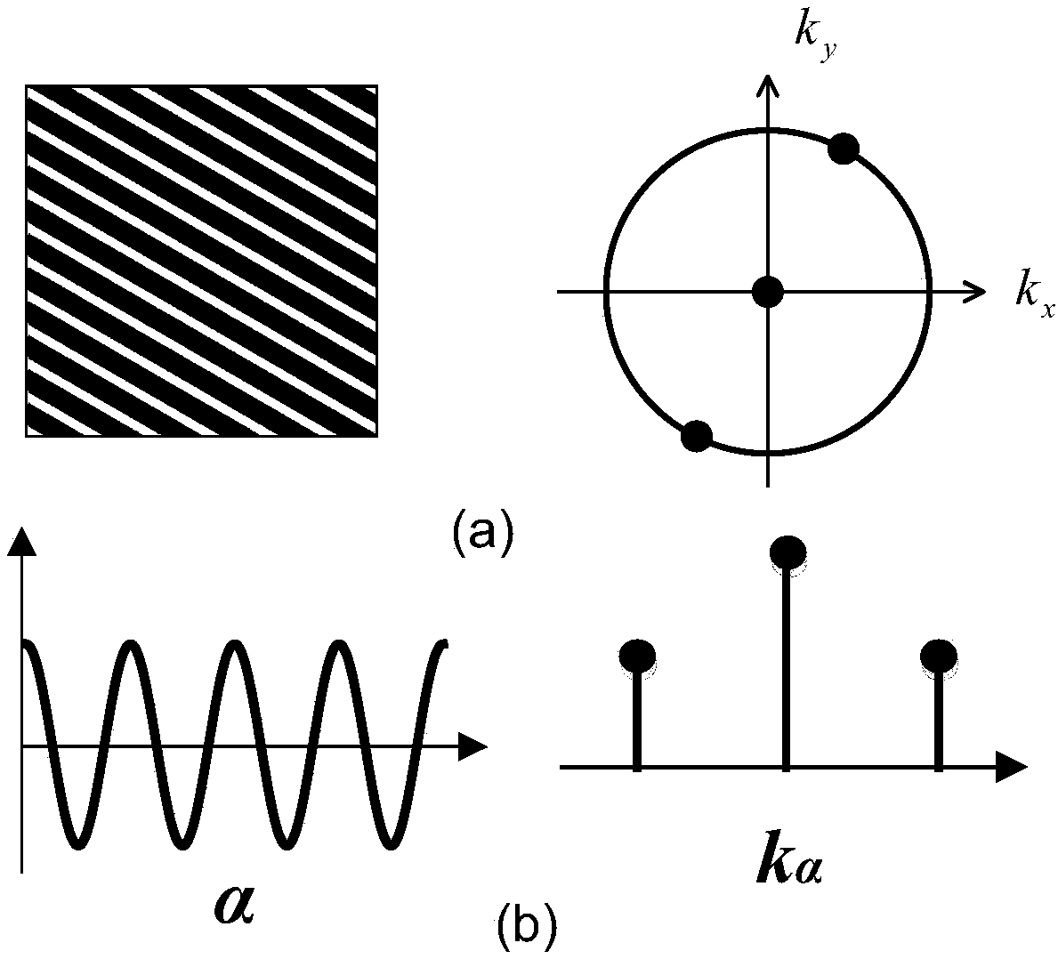
[0024] The point spread function of an ordinary optical system is usually a Gaussian spot, which acts as a low-pass filter in the frequency domain. Since the collected pictures can be regarded as the convolution of the fluorescence sample information and the system point spread function, the ordinary imaging process can be regarded as frequency selection in the frequency domain. Due to the loss of high-frequency information, the small-scale change information in the air domain cannot be obtained, and the resolution of the system is limited. Therefore, after structured light irradiation, the optical transfer function of the system is widened in the frequency domain in t...


PUM


Abstract

The invention relates to a structured light illumination-based fluorescent dipole orientation method. The method is characterized by comprising the following steps of 1) obtaining an original image and modulation information of a fluorescent sample with a polarization property by adopting a structured light microscopic system, and obtaining spatial frequency domain components corresponding to different spatial angles, wherein the original image refers to a fluorescent sample image collected through a camera sensor of the structured light microscopic system, and the modulation information refers to modulation intensity, a phase and a spatial angle of the structured light microscopic system; 2) performing spatial dimensional frequency domain splicing on all the spatial frequency domain components to obtain a two-dimensional super-resolution spatial image of the fluorescent sample, and expanding angular dimensional frequency domains of all the spatial frequency domain components to obtainpolarization angle information of the fluorescent sample; and 3) performing matching on the two-dimensional super-resolution spatial image of the fluorescent sample and the polarization angle information to obtain a super-resolution fluorescent dipole orientation result.

Description

technical field [0001] The invention relates to a fluorescent dipole orientation method based on structured light illumination, and relates to the technical field of super-resolution fluorescent microscopy. Background technique [0002] Fluorescence microscopy is an important tool in life science research. In life science research, the region of interest is often fluorescently marked. After it is irradiated by excitation light, the emitted fluorescence will contain the structure and function information of the organism, providing the possibility for further research. However, common fluorescence microscopy systems use two-dimensional camera sensors to collect signals, which can only obtain spatial information of samples. Most of the fluorescent molecules are dipoles, and the fluorescence emitted by them often has strong polarization characteristics, and this part of the characteristics will be lost. In fact, polarization information can reflect the structural characteristi...

Claims


Application Information

Patent Timeline
Patent Type & Authority Applications(China)
IPC IPC(8): G06T3/40G06T7/60G06K9/62
CPCG06T3/4038G06T7/60G06T2207/10056G06T2207/10064G06F18/22
Inventor 张昊陈星晔戴琼海席鹏
Owner 北京艾锐精仪科技有限公司
Why Eureka
Try Eureka