
Difunctional reaction equipment

A reaction equipment and dual-function technology, applied in the direction of gaseous chemical plating, coating, electrical components, etc., can solve the problems of single function and low utilization efficiency, and achieve the effects of improving utilization efficiency, easy operation and convenient control

Pending Publication Date: 2018-05-15
楚赟精工科技(上海)有限公司
View PDF0 Cites 0 Cited by
  • Summary
  • Abstract
  • Description
  • Claims
  • Application Information

AI Technical Summary

Problems solved by technology

[0006] In view of the above-mentioned shortcomings of the prior art, the purpose of the present invention is to provide a dual-function reaction equipment, which is used to solve the problems of single function and low utilization efficiency of the tube furnace equipment in the prior art.

Method used


Image

  • Difunctional reaction equipment
  • Difunctional reaction equipment
  • Difunctional reaction equipment

Examples


Embodiment Construction

[0112] Embodiments of the present invention are described below through specific examples, and those skilled in the art can easily understand other advantages and effects of the present invention from the content disclosed in this specification. The present invention can also be implemented or applied through other different specific implementation modes, and various modifications or changes can be made to the details in this specification based on different viewpoints and applications without departing from the spirit of the present invention.

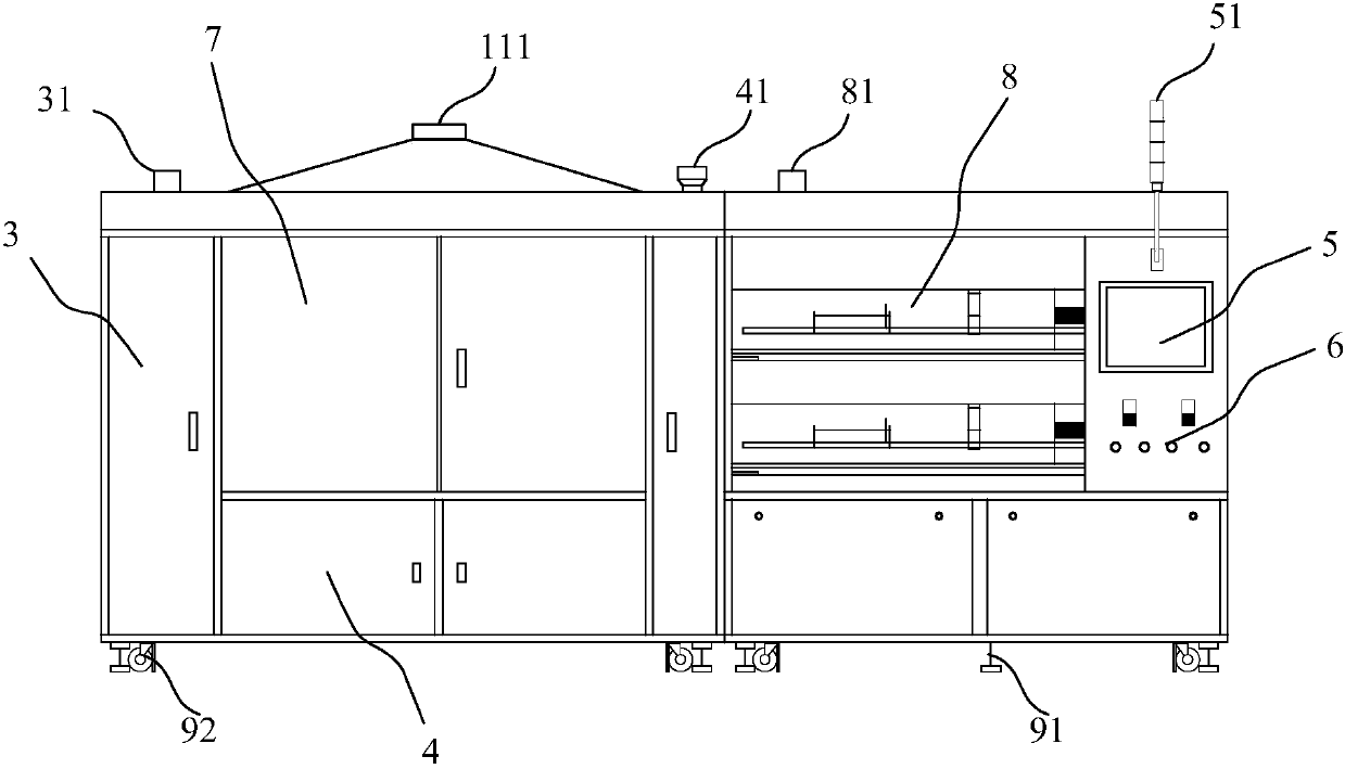
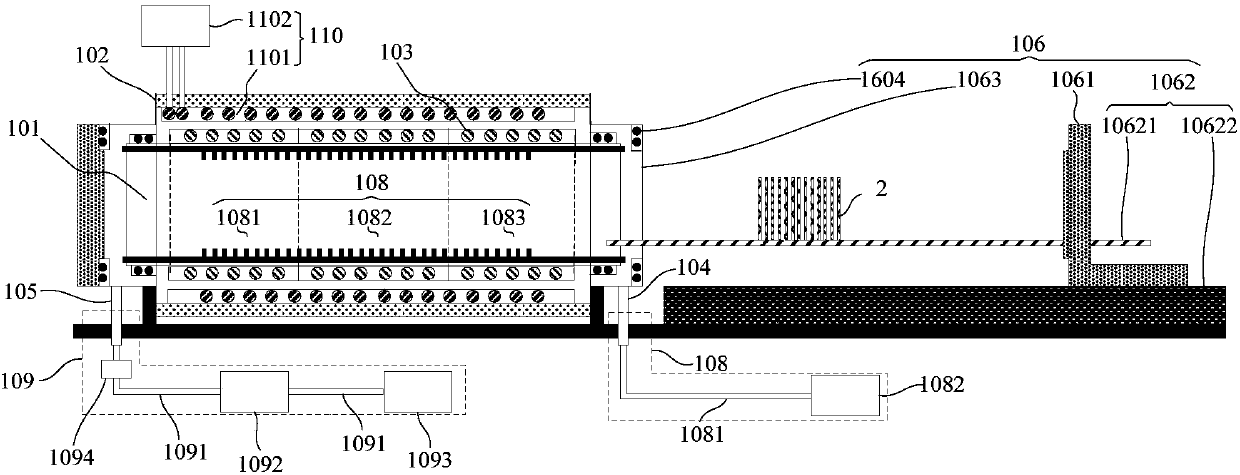
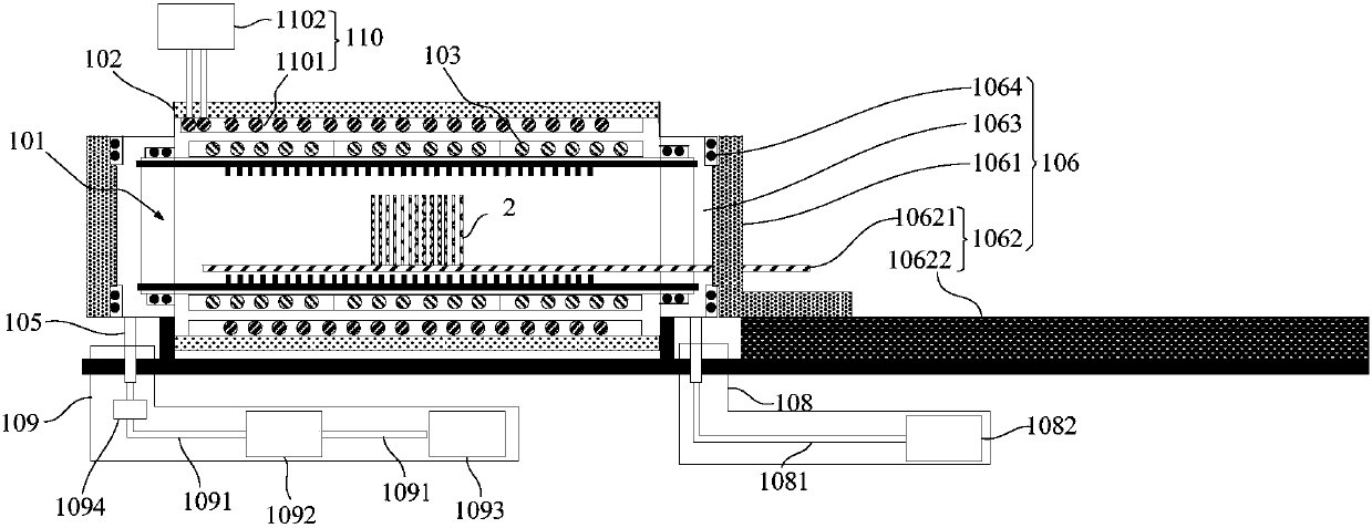
[0113] see Figure 1 to Figure 9 . It should be noted that the diagrams provided in this embodiment are only schematically illustrating the basic idea of ​​the present invention, and only the components related to the present invention are shown in the diagrams rather than the number, shape and shape of the components in actual implementation. Dimensional drawing, the type, quantity and proportion of each component can be changed arb...


PUM


Abstract

The invention provides difunctional reaction equipment. The difunctional reaction equipment comprises a difunctional reaction furnace, an air source cabinet and an air exhaust cabinet, wherein the difunctional reaction furnace is used for growing and etching a material layer on the surface of a to-be-treated substrate, the difunctional reaction furnace comprises a furnace tube used for placing theto-be-treated substrate, a furnace body, a heating device, an air inlet component which is communicated with the interior of the furnace tube and is used for introducing growth gas or etching gas into the furnace tube, an air outlet, a furnace door component used for communicating or isolating the furnace tube with or from the outside and introducing in or taking out the to-be-treated substrate,an air supply system and an air exhaust system. The difunctional reaction equipment provided by the invention can grow the material layer on the surface of the to-be-treated substrate and also can etch the material on the surface of the to-be-treated substrate, thereby having growing and etching dual functions; and the furnace door component in the difunctional reaction furnace can realize loadingand unloading of the to-be-treated substrate at high temperature, and cooling to room temperature does not need to be carried out after the substrate is treated, so that utilization efficiency of thedifunctional reaction equipment is obviously increased.

Description

technical field [0001] The invention relates to the technical field of reaction equipment, in particular to a dual-function reaction equipment. Background technique [0002] Currently commonly used thin film growth equipment includes MOCVD, PECVD, and tube furnaces. Among them, the equipment of MOCVD and PECVD is expensive, the maintenance cost is high, and the process is complicated and the production efficiency is low. The cost of tube furnace equipment is low, and it can accommodate batches of reactants for reaction at one time. However, due to the limitation of equipment process conditions, its application range is narrow, and it is limited to film growth or annealing under specific atmospheric conditions. [0003] The current tube furnace equipment generally can only support the growth reaction of the material layer on the surface of the reactant, but cannot support the etching reaction for removing the material layer on the surface of the reactant because the equipmen...

Claims


Application Information

Patent Timeline
IPC IPC(8): H01L21/67C23C16/455C23C16/458
CPCH01L21/6719C23C16/455C23C16/4582
Inventor 不公告发明人
Owner 楚赟精工科技(上海)有限公司
Learn More