Brick setting robot gripper

A technology of robot and brick stacking, which is applied in the field of gripping hands of the brick stacking robot, can solve the problems of easily damaged bricks, affecting brick-making production efficiency, and long shrinkage time.

Inactive Publication Date: 2012-08-01
重庆信奇建材机械制造有限公司
View PDF7 Cites 6 Cited by
  • Summary
  • Abstract
  • Description
  • Claims
  • Application Information

AI Technical Summary

Problems solved by technology

However, the machine gripper at one end moves closer to the other, and the moving stroke of the machine gripper is relatively large, so the shrinkage time is longer, which affects the production efficiency of br...

Method used


Image

  • Brick setting robot gripper
  • Brick setting robot gripper
  • Brick setting robot gripper

Examples


Embodiment Construction

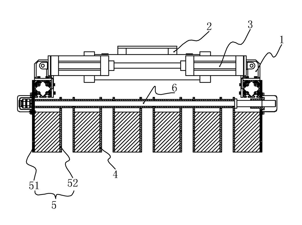
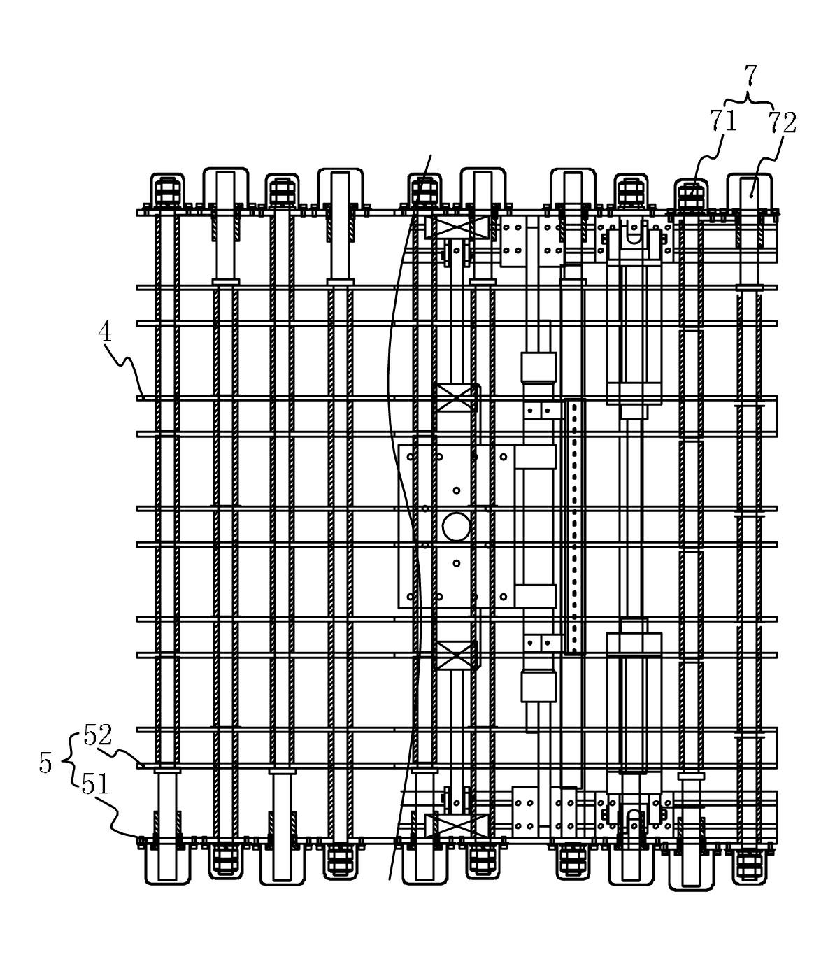
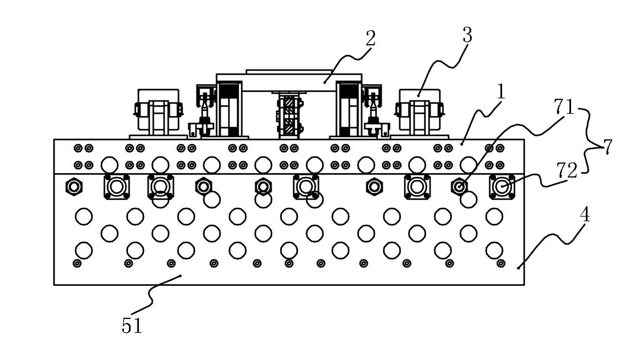
[0013] Such as figure 1 , 2 and image 3 As shown, the gripper of the brick-coding robot of the present invention includes a top frame body 1 on which a mounting base 2 and a pneumatic device 3 are fixed through guide rails, and a machine gripper is connected to the bottom of the top frame body 1 . The machine gripper includes an even number of splints 4, the splints 4 are parallel to each other and vertically arranged, every two adjacent splints 4 form a splint group 5, and each splint group is composed of a left splint 51 and a right splint 52 . There are pull rods 6 transversely running through the gripper of the machine, and every two groups of the pull rods 6 form four groups of drive pull rods 7, and the drive pull rods 7 include a left drive pull rod 71 and a right drive pull rod 72, and the left drive pull rod 71 is fixed with the left splint 51 of each splint group 5, and cooperates with the right splint 52 of each splint group in clearance; Cooperate.

[0014] T...


PUM


Abstract

The invention discloses a brick setting robot gripper which comprises an even number of clamp plates, wherein the clamp plates are parallel to each other and arrayed vertically; the clamp plates at two ends are fixed on a top frame body and connected with a flexible power device; every two clamp plates form a group; each group of clamp plates comprises a left clamp plate and a right clamp plate; pull rods transversely penetrate through the clamp plates; the pull rods comprise at least one group of driving pull rods which comprise a left driving pull rod and a right driving pull rod; the left driving pull rod is fixed with the left clamp plate of each group of clamp plates and in interference fit with the right clamp plate of each group of clamp plates; and the right driving pull rod is fixed with the right clamp plate of each group of clamp plates and in interference fit with the left clamp plate of each group of clamp plates. The clamp plates of the device move at the same time, so that the horizontal positions of green bricks do not change in the clamping process, no horizontal displacement occurs, the green bricks are clamped without being moved, safety and convenience are provided, and the green bricks are not easy to damage.

Description

technical field [0001] The invention relates to a mechanical arm for clamping and stacking bricks, in particular to the clamping hand of the robot for clamping and stacking bricks. Background technique [0002] The brick clamping mechanism of the palletizer includes a beam on which a plurality of machine grippers are distributed, and the bricks pressed from the brick mold are clamped by the machine grippers. Since molds are needed in the process of pressing bricks, therefore, There is a gap between each block of adobe. If the gap is not eliminated during the stacking process, the brick stack will easily collapse, and the number of stacking layers will be reduced, which is convenient for roasting in the kiln, and the stacking area is large. Therefore, the machine grippers distributed on the crossbeam of the existing palletizers are all distributed at intervals, and at the same time, the retraction mechanism of the machine grippers along the direction of the crossbeam must be ...

Claims


Application Information

Patent Timeline
IPC IPC(8): B65G61/00
Inventor 张信聪黄书荣
Owner 重庆信奇建材机械制造有限公司
Why Eureka
Try Eureka