
Universal self-adaptive wave trapper
An adaptive notch filter and dynamic equation technology, applied in the field of electrical variable measurement, can solve the problems of ANF performance degradation and achieve the effect of simple structure and wide adaptability
- Summary
- Abstract
- Description
- Claims
- Application Information
AI Technical Summary
Problems solved by technology
Method used
Image

Examples
specific Embodiment 1
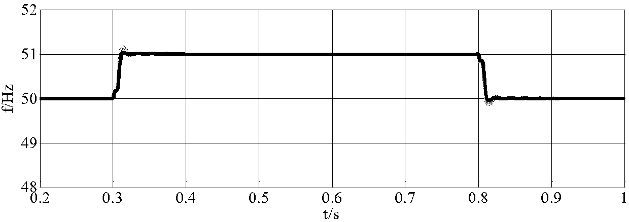
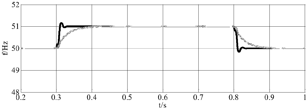
[0056] Specific embodiment 1, it is assumed that the frequency of the input signal is 50 Hz, the initial phase angle is 0, ε=500, and ζ=0.6. First set the input signal amplitude as 1.0pu, when t=0.3s, the input signal frequency increases to 51Hz, and when t=0.8s, the frequency returns to 50Hz. The frequency tracking results obtained by using general ANF and traditional ANF are as follows figure 2 As shown, the black line in the figure is the detection waveform of general ANF, and the gray line is the detection waveform of traditional ANF. It can be seen that both methods can quickly and accurately detect frequency changes when the input signal amplitude is 1.0pu.
[0057] Set the amplitude of the input signal to 0.5pu and 1.5pu respectively, and the frequency still changes as described above, the result obtained is as follows image 3 and 4 shown. The results show that the detection performance of the general-purpose ANF designed in this paper is always consistent when the...
specific Embodiment 2
[0058] In the specific embodiment 2, it is assumed that the frequency of the input signal is 400 Hz, the initial phase angle is 0, ε=500, and ζ=0.6. First set the input signal amplitude to 1.0pu, when t=1.0s, the input signal frequency increases to 800Hz, and when t=1.6s, the frequency returns to 400Hz. The frequency tracking results obtained by using general ANF and traditional ANF are as follows Figure 5 As shown, the black line in the figure is the detection waveform of the general ANF, and the gray line is the detection waveform of the traditional ANF. It can be seen that the general ANF can track the frequency change in one cycle, while the traditional ANF takes a long time to detect the frequency There is a large difference in speed between the two.
[0059] Set the input signal amplitudes to 0.5pu and 1.5pu respectively. When t=2.0s, the input signal frequency increases to 800Hz. When t=4.0s, the frequency returns to 400Hz. The waveform is as follows Figure 6 and 7...
specific Embodiment 3
[0061] In the specific embodiment 3, it is assumed that the frequency of the input signal is 50 Hz, the initial phase angle is 0, ε=500, and ζ=0.6. First set the amplitude of the input signal to be 1.0pu. When t=0.3s, the amplitude is increased by 0.2pu, and when t=0.8s, the amplitude is restored to 1.0pu. The amplitude tracking results obtained by using general ANF and traditional ANF are as follows: Figure 8 As shown, the black line in the figure is the detection waveform of the general ANF, and the gray line is the detection waveform of the traditional ANF. It can be seen that both methods can quickly and accurately detect the amplitude change when the input signal amplitude is 1.0pu.
[0062] Set the input signal amplitudes as 0.5pu and 1.5pu respectively, when t=0.3s, the amplitudes increase to 0.6pu and 1.8pu respectively, the obtained results are as follows Figure 9 and 10 shown. The results show that the amplitude detection performance of the general-purpose ANF ...
PUM
 Abstract
Description
Claims
Application Information