
Multi-mode imaging system

A multi-mode imaging and subsystem technology, applied in the field of medical imaging, can solve the problems of low image resolution, large radiation dose, and small imaging depth, and achieve the effect of high image resolution, low radiation dose, and large imaging depth.

Pending Publication Date: 2018-05-18
SHENZHEN INST OF ADVANCED TECH
View PDF0 Cites 6 Cited by
  • Summary
  • Abstract
  • Description
  • Claims
  • Application Information

AI Technical Summary

Problems solved by technology

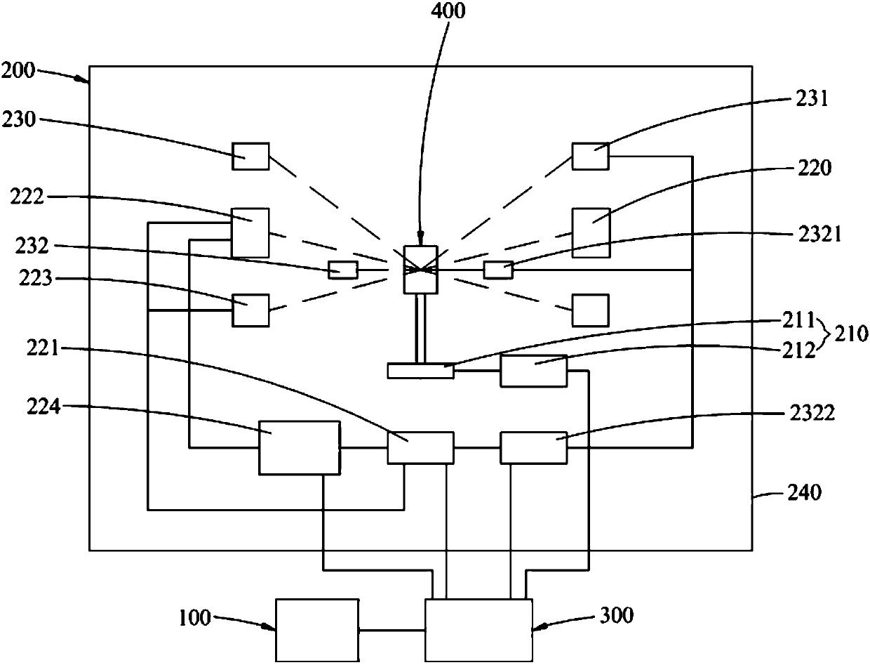
[0006] The purpose of the present invention is to provide a multi-mode imaging system, which aims to solve the technical problems of low image resolution, small imaging depth and large radiation dose in the specific application of the existing small animal living body multi-mode imaging technology

Method used


Image

  • Multi-mode imaging system
  • Multi-mode imaging system

Examples


Embodiment Construction

[0032] The following will clearly and completely describe the technical solutions in the embodiments of the present invention with reference to the accompanying drawings in the embodiments of the present invention. Obviously, the described embodiments are only part of the embodiments of the present invention, not all of them. Based on the embodiments of the present invention, all other embodiments obtained by persons of ordinary skill in the art without creative efforts fall within the protection scope of the present invention.

[0033] It should be noted that all directional indications (such as up, down, left, right, front, back...) in the embodiments of the present invention are only used to explain the relationship between the components in a certain posture (as shown in the accompanying drawings). Relative positional relationship, movement conditions, etc., if the specific posture changes, the directional indication will also change accordingly.

[0034] It should also be...


PUM


Abstract

The invention is applicable to the technical field of medical images, and discloses a multi-mode imaging system. The multi-mode imaging system comprises a display, multi-mode imaging equipment and a mainframe electrically connected between the display and the multi-mode imaging equipment, the mainframe is internally provided with an image rebuilding and processing subsystem, the multi-mode imagingequipment is internally provided with an animal scanning control subsystem, a static computer tomography subsystem and a photoacoustic imaging subsystem, the static computer tomography subsystem comprises an electronic control circuit, a multi-beam carbon nano X-ray source array used for generating X-rays needed by static computer tomography scanning, a photon counting detector used for computertomography projection data acquisition and high-speed processing and a power supply used for supplying power to the multi-beam carbon nano X-ray source array, and the multi-beam carbon nano X-ray source array, the photon counting detector and the power supply are all electrically connected with the electronic control circuit. The multi-mode imaging system is high in image resolution, large in imaging depth and low in radiation dose.

Description

technical field [0001] The invention relates to the technical field of medical imaging, in particular to a multimode imaging system. Background technique [0002] Cancer is the most common type of malignant tumors, and it is the number one killer threatening human health. At present, the global cancer cases are showing a rapid growth trend, and the new cases are mainly from developing countries. Due to the characteristics of high mortality, high disability rate and large medical burden, malignant tumors have become a public health problem and even a social problem that must be paid close attention to all over the world. Among the lethal factors caused by cancer, tumor metastasis is the most important factor. [0003] At present, studies on tumor metastasis are mainly carried out on small animals represented by mice and rats. In specific research, first establish tumor disease models in small animals, and then study the physiological-pathological characteristics of tumor m...

Claims


Application Information

Patent Timeline
IPC IPC(8): A61B5/00A61B6/03
CPCA61B5/0035A61B5/0095A61B6/032A61B6/4411A61B6/5235A61B6/5247A61B2503/42A61B2503/40
Inventor 梁栋洪序达石伟龚小竞刘成波胡战利林日强郑海荣
Owner SHENZHEN INST OF ADVANCED TECH
Learn More