Special lathe for shaft part machining

A technology for shaft parts and special lathes, applied in the field of machinery, can solve the problems of uneven processing force, affecting the coaxiality and step surface verticality of shaft parts, and reducing the processing quality of shaft parts, so as to improve processing Quality, good coaxiality and verticality of the step surface, reasonable effect of clamping force distribution

Inactive Publication Date: 2018-05-18
凤城市时代龙增压器制造有限公司
View PDF10 Cites 1 Cited by
  • Summary
  • Abstract
  • Description
  • Claims
  • Application Information

AI Technical Summary

Problems solved by technology

This processing method will lead to uneven machining of the shaft, which will affect the coaxiality of the shaft parts and the verticality of the step surface, resulting in a reduction in the processing quality of the shaft parts and even defective products.

Method used


Image

  • Special lathe for shaft part machining
  • Special lathe for shaft part machining
  • Special lathe for shaft part machining

Examples


Embodiment Construction

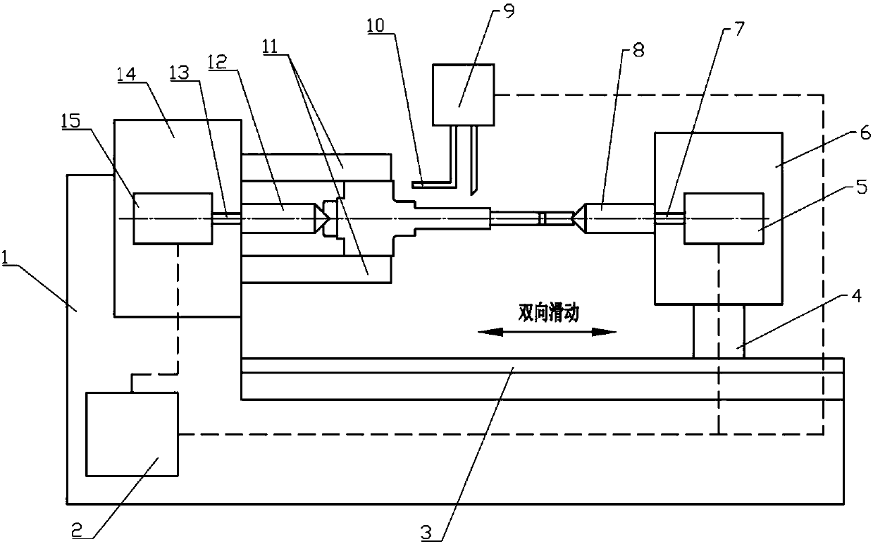
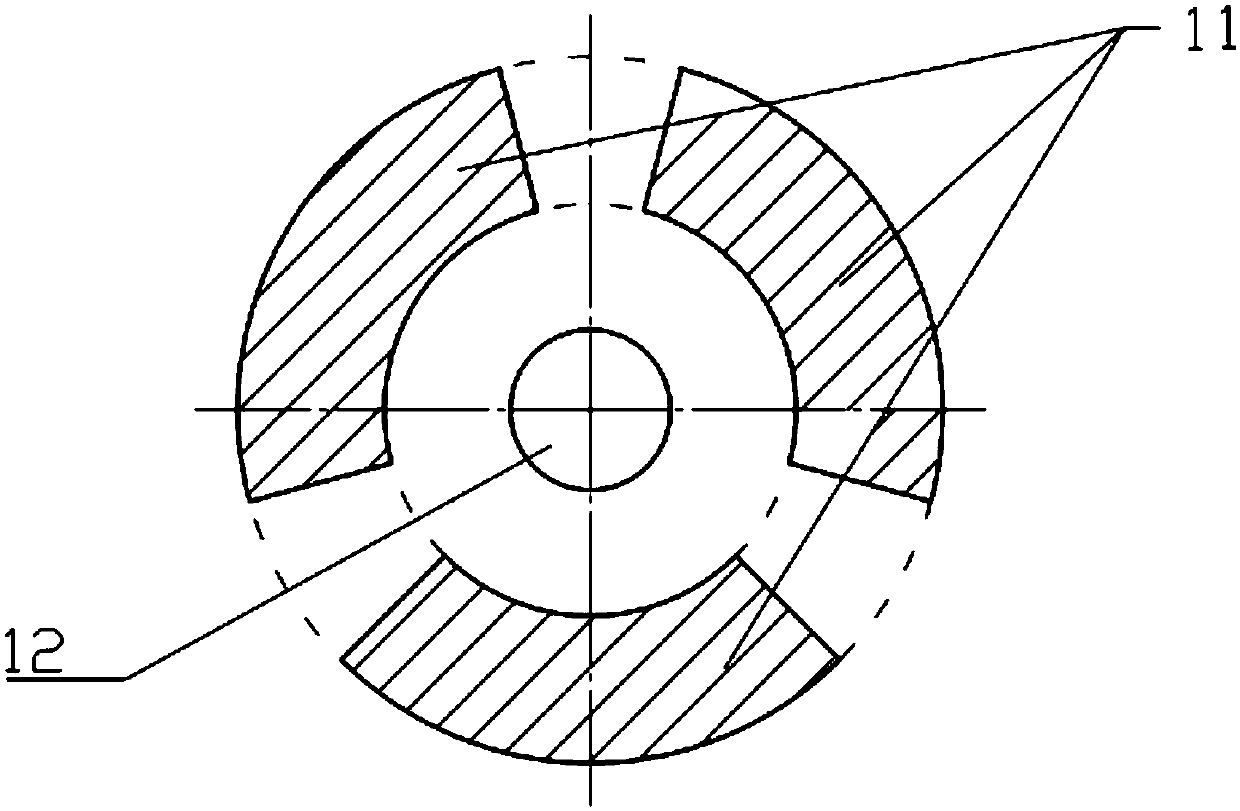
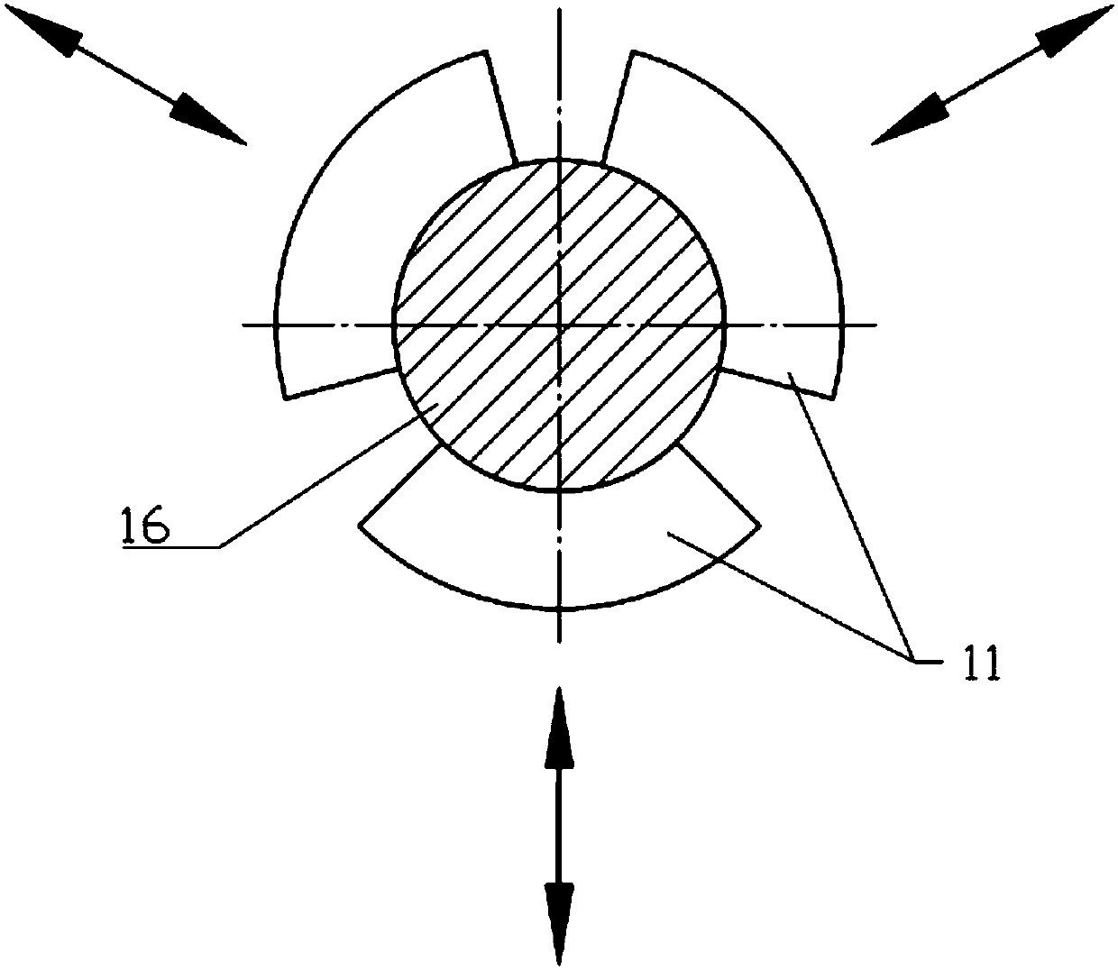
[0017] Such as figure 1 As shown, a special lathe for processing shaft parts, including a bed 1, a guide rail 3, a first headstock 14, a second headstock 6, a frame 4, a first spindle 14, a second spindle 7, a first center 12. The second top 8, the first power motor 15, the second power motor 5, the tool holder mechanism 9, the centerless radial clamp 11 and the control system 2, and the bed 1 is provided with a first headstock 14 and a guide rail 3 And tool post mechanism 9, described guide rail 3 is provided with frame 4, and described frame 4 is provided with second headstock 6; Described first headstock 14 is provided with first power motor 15, and described first The output end of a spindle box 14 is provided with a first spindle 13, and the first spindle 13 is provided with a first top 12 and a centerless radial clamp 11; the second spindle box 6 is provided with a second power motor 5, The output end of the second spindle box 6 is provided with a second main shaft 7, a...


PUM


Abstract

The invention relates to a special lathe for shaft part machining. According to the technical scheme, the special lathe for shaft part machining comprises a lathe bed, a guide rail, a first spindle box, a second spindle box, a machine frame, a first spindle, a second spindle and a first center, a second center, a first power motor, a second power motor, a knife rest mechanism and a centerless radial clamp, wherein the first spindle box, the guide rail and the knife rest mechanism are arranged on the lathe bed, a machine frame is arranged on the guide rail, and the second spindle box is arranged on the machine frame; the first power motor is arranged in the first spindle box, the first spindle is arranged at the output end of the first spindle box, and the first center and the centerless radial clamp are arranged on the first spindle; and the second power motor is arranged in the second spindle box, the second spindle is arranged at the output end of the second spindle box, and the second center is arranged on the second spindle. According to the special lathe for shaft part machining, the machined shaft part can be guaranteed to have good coaxiality and step surface perpendicularity.

Description

technical field [0001] The invention belongs to the field of machinery, and in particular relates to a special lathe for machining shaft parts. Background technique [0002] Shaft parts are key components for torque transmission and rotational motion transmission of various mechanical equipment. Manufacturing and processing technology is the key to the reliability and design performance of mechanical equipment, and the machining accuracy of shaft parts has an important impact on the performance, efficiency and service life of corresponding mechanical equipment. Therefore, modern machinery and equipment have high requirements on the machining accuracy of shaft parts, especially in terms of coaxiality and verticality of the step surface. [0003] Traditional shaft parts are processed on a general-purpose CNC lathe. One end of the shaft is clamped by a three-jaw chuck, and the center of the other end of the shaft is placed on the top of the tailstock; during processing, the to...

Claims


Application Information

Patent Timeline
Patent Type & Authority Applications(China)
IPC IPC(8): B23B5/08
CPCB23B5/08
Inventor 范厚传曲大勇
Owner 凤城市时代龙增压器制造有限公司
Why Eureka
Try Eureka