

Electric chuck based on worm rod
A worm and rotating disk technology, applied in the field of electric chucks, can solve the problems of high repeatability and high labor intensity, and achieve the effects of compact structure, reduced labor costs, and improved work efficiency
- Summary
- Abstract
- Description
- Claims
- Application Information
AI Technical Summary
Problems solved by technology
Method used
Image

Examples
Embodiment Construction
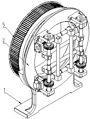
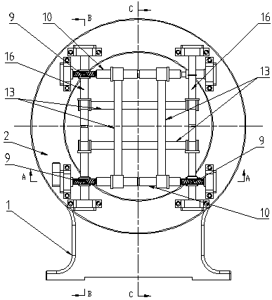
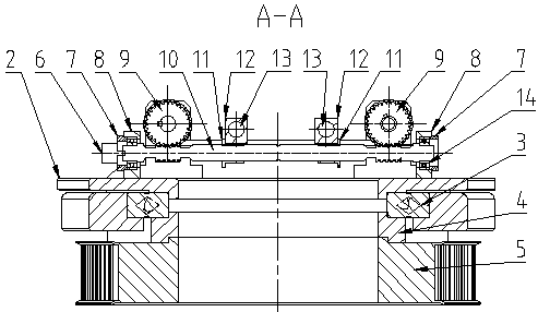
[0008] An electric chuck based on a worm, consisting of 1 base, 2 rotating discs, 3 crossed roller guide rails, 4 connecting discs, 5 synchronous pulleys, 6 motors, 7 end covers, 8 bearing housings 1, 9 worm gears, 10 worms Ball screw shaft, 11 screw nut, 12 optical axis seat, 13 optical axis, 14 bearing, 15 bearing seat II, 16 worm gear shaft, 17 sleeve, characterized in that: 2 rotating discs are positioned on 3 cross roller guide rails The inner wall is fixed on the inner wall of the 3 cross roller guide, the outer wall of the 3 cross roller guide is fixed in the inner hole of the base 1, the 4 connecting plate is fixed on the inner wall of the 3 cross roller guide on one side, and the other side is fixed on the 5 synchronous pulley , 8 bearing housings I and 9 bearing housings II are fixed on the 2 rotating disk, 6 motors are installed on the 7 end covers, 6 motor output shafts are connected to one end of the 10 worm ball screw shaft, and both ends of the 10 worm ball screw...
PUM
 Abstract
Description
Claims
Application Information