Boring head for machining cylinder tube of hydraulic cylinder

A technology of hydraulic cylinders and cylinders, applied in boring heads, metal processing equipment, metal processing machinery parts, etc., can solve the problems of reduced production efficiency, increased production costs, low service life, etc., to extend service life and save production costs. Effect

Pending Publication Date: 2018-05-18
HENAN AIZTO SCI & TECH CO LTD
View PDF6 Cites 1 Cited by
  • Summary
  • Abstract
  • Description
  • Claims
  • Application Information

AI Technical Summary

Problems solved by technology

The iron filings cut by the cutting tool will affect the movement of the boring head, resulting in reduced production efficiency and even damage to the boring head. Currently, in the production process, a flushing device is installed in front of the boring head to flush the iron filings, but the flushing effect is not good. Moreover, the cutting tool of the boring head is easily damaged by overheating, and the service life is low, which increases the production cost

Method used


Image

  • Boring head for machining cylinder tube of hydraulic cylinder
  • Boring head for machining cylinder tube of hydraulic cylinder

Examples


Embodiment 1

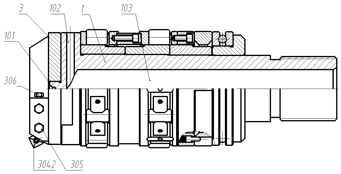
[0014] Such as Figure 1 to Figure 2 As shown, a boring head for machining hydraulic cylinder barrels includes a hollow mandrel 1 driven by a geared motor and a cutter head 3 mounted on the hollow mandrel 1 through connecting bolts 2 . The cutter head 3 is moved by the movement of the hollow mandrel 1 .

[0015] One end of the hollow mandrel 1 is closed, and the other end is open.

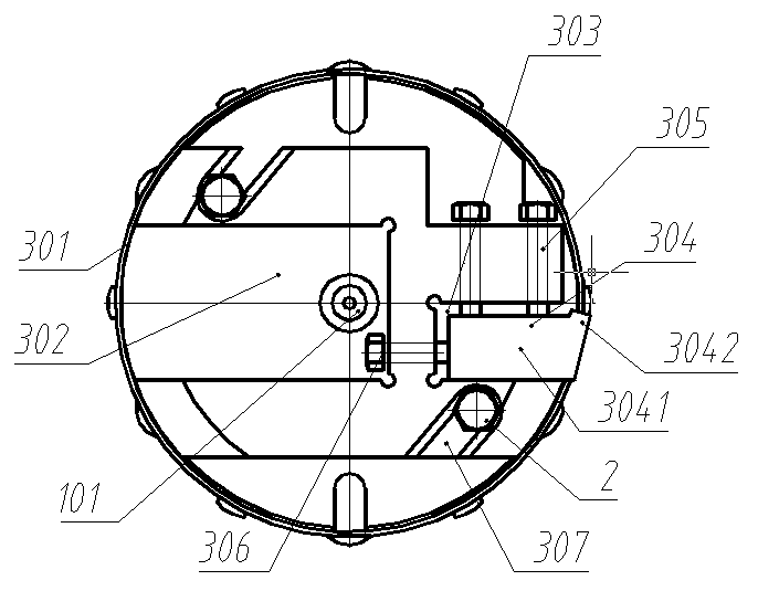
[0016] The cutter head 3 includes a disc body 301, one side of the disc body 301 is provided with a groove 302, and the other side is provided with a locking groove 303, and the middle part of the groove 302 is provided with a limiting through hole that runs through the disc body 301. The limiting through hole is matched with the limiting shaft 101 arranged at the closed end of the hollow mandrel 1 .

[0017] A cutting knife 304 is arranged in the slot 303, and a knife handle 3041 of the cutting knife 304 is fixed in the slot 303 by a fastening bolt 305. The cutter head 3042 of the cutting knife ...

Embodiment 2

[0027] Such as Figure 1 to Figure 2 As shown, a boring head for machining hydraulic cylinder barrels includes a hollow mandrel 1 driven by a geared motor and a cutter head 3 mounted on the hollow mandrel 1 through connecting bolts 2 . The cutter head 3 is moved by the movement of the hollow mandrel 1 .

[0028] One end of the hollow mandrel 1 is closed, and the other end is open.

[0029] The cutter head 3 includes a disc body 301, one side of the disc body 301 is provided with a groove 302, the groove 302 is cylindrical, and the other side is provided with a card slot 303, and the middle part of the groove 302 is provided with a through disk The limiting through hole provided on the body 301 is matched with the limiting shaft 101 arranged at the closed end of the hollow mandrel 1 .

[0030] A cutting knife 304 is arranged in the slot 303, and a knife handle 3041 of the cutting knife 304 is fixed in the slot 303 by a fastening bolt 305. The cutter head 3042 of the cutting k...

Embodiment 3

[0040] Such as Figure 1 to Figure 2 As shown, a boring head for machining hydraulic cylinder barrels includes a hollow mandrel 1 driven by a geared motor and a cutter head 3 mounted on the hollow mandrel 1 through connecting bolts 2 . The cutter head 3 is moved by the movement of the hollow mandrel 1 .

[0041] One end of the hollow mandrel 1 is closed, and the other end is open.

[0042] The cutter head 3 includes a disc body 301, one side of the disc body 301 is provided with a groove 302, and the other side is provided with a locking groove 303, and the middle part of the groove 302 is provided with a limiting through hole that runs through the disc body 301. The limiting through hole is matched with the limiting shaft 101 arranged at the closed end of the hollow mandrel 1 .

[0043] A cutting knife 304 is arranged in the slot 303, and a knife handle 3041 of the cutting knife 304 is fixed in the slot 303 by a fastening bolt 305. The cutter head 3042 of the cutting knife ...


PUM


Abstract

A boring head for machining a cylinder tube of a hydraulic cylinder comprises a hollow core shaft driven to rotate through a gear motor and a cutter disc mounted on the hollow core shaft through connecting bolts. One end of the hollow core shaft is closed, and the other end of the hollow core shaft is open. The cutter disc comprises a disc body, a groove is formed in one side of the disc body, anda clamping groove is formed in the other side of the disc body. A limiting through hole penetrating through the disc body is formed in the middle of the groove and matched with a limiting shaft arranged at the closed end of the hollow core shaft, a cutter is arranged in the clamping groove, and a shank of the cutter is fixed into the clamping groove through a fastening bolt. A cutting head of thecutter extends out of the cutter disc so as to cut the inner wall of the cylinder tube in the rotating process, a plurality of liquid passing holes are formed in the circumferential wall face of theclosed end of the hollow core shaft, and the liquid passing holes communicate with a hollow cavity of the hollow core shaft.

Description

technical field [0001] The invention relates to the technical field of mechanical processing, in particular to a boring head for processing cylinder barrels of hydraulic cylinders. Background technique [0002] The boring head can be used to process the cylinder of the hydraulic cylinder. The boring head generally includes a cutterhead and a mandrel that drives the cutterhead to rotate. A cutting knife is installed on the cutterhead. The cutting knife moves in a circle with the cutterhead to cut the inner wall of the cylinder. , the cutter head rotates once, and the cutter completes one round of cutting. The iron filings cut by the cutting tool will affect the movement of the boring head, resulting in reduced production efficiency and even damage to the boring head. Currently, in the production process, a flushing device is installed in front of the boring head to flush the iron filings, but the flushing effect is not good. And the cutting tool of the boring head is easily ...

Claims


Application Information

Patent Timeline
Patent Type & Authority Applications(China)
IPC IPC(8): B23Q11/02B23B29/03
CPCB23B29/03B23Q11/02
Inventor 叶元朋赵超越郭晓伟于胜鸽
Owner HENAN AIZTO SCI & TECH CO LTD
Why Eureka
Try Eureka