Bell valve self-lifting system and working method thereof

An automatic lifting and bell valve technology, which is applied in the direction of fluid pressure actuated system components, valve operation/release devices, lifting valves, etc., can solve the problems of bell valve leakage, bell opening and closing degree cannot be accurately controlled, etc. Achieve the effect of preventing smoke and dust from entering and good sealing effect

Inactive Publication Date: 2018-05-18
TONGLING QIUJING MACHINERY
View PDF1 Cites 0 Cited by
  • Summary
  • Abstract
  • Description
  • Claims
  • Application Information

AI Technical Summary

Problems solved by technology

[0002] The switching of the bypass flue gas under the heat preservation condition of the existing Austrian furnace and electric furnace is realized through the bell valve. Due to the high temperature of the Austrian furnace and the electric furnace, the switching process needs to be realized through an automatic control system. The practical patent No. 97228308.0 The new patent discloses a starting bell valve, the bell valve realizes the automatic opening and closing of the bell through the pneumatic valve stem, but the degree of opening and closing of the bell cannot be precisely controlled, which may easily cause leakage of the bell valve, etc.

Method used


Image

  • Bell valve self-lifting system and working method thereof
  • Bell valve self-lifting system and working method thereof
  • Bell valve self-lifting system and working method thereof

Examples


Embodiment Construction

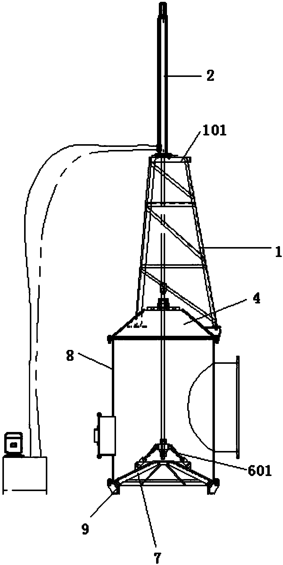
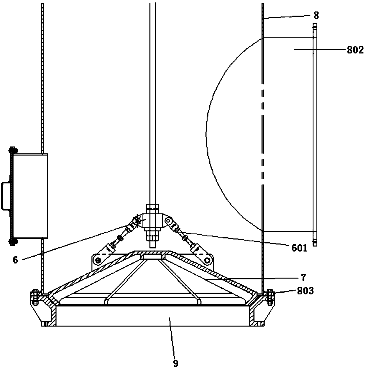
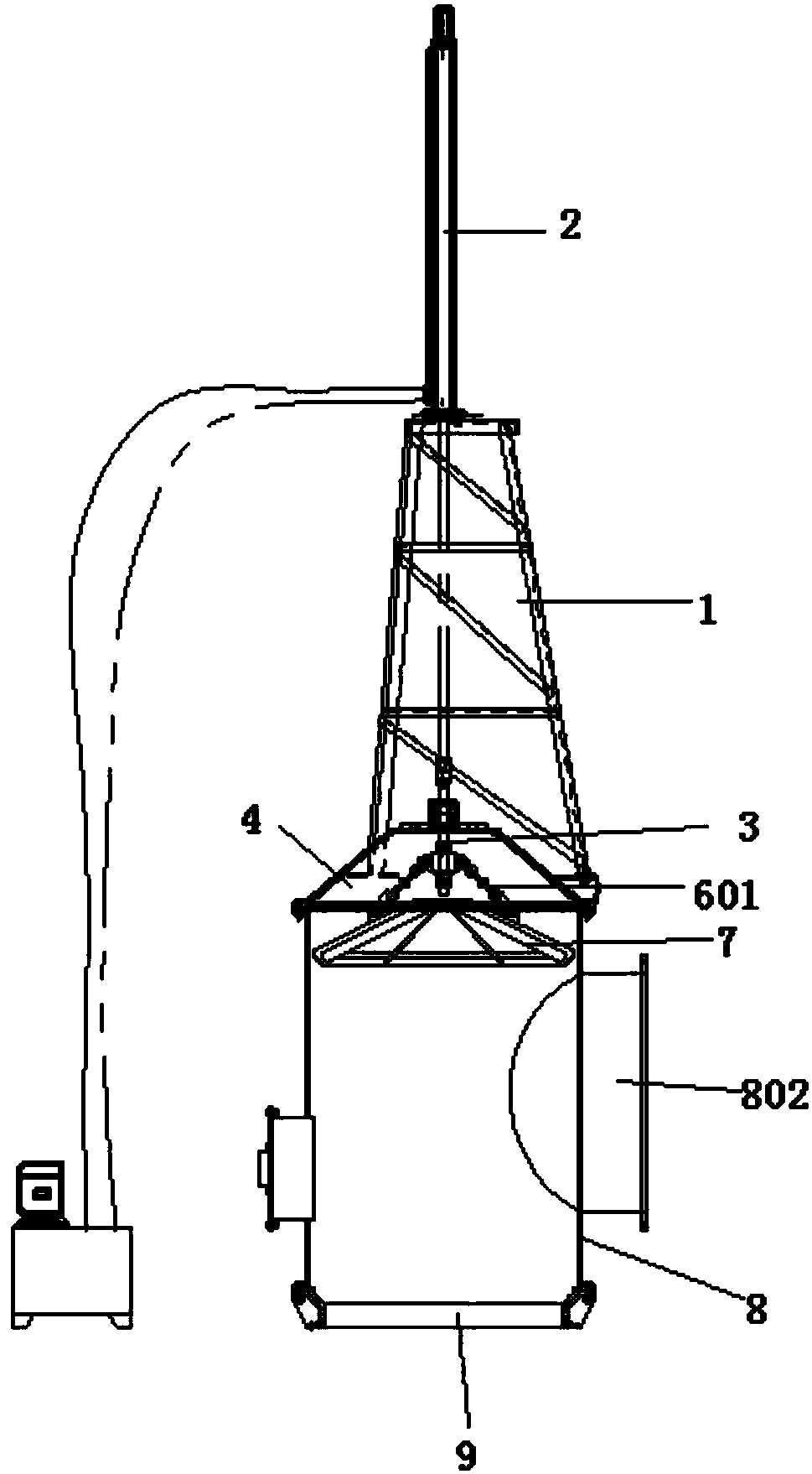
[0029] A bell valve automatic lifting system, such as figure 1 , figure 2 , image 3 , Figure 4 , Figure 5 and Figure 6 As shown, it includes a triangular support 1, a triangular support plate 101 is fixed on the top of the triangular support 1, a through hole is provided at the center of the surface of the triangular support plate 101, a hydraulic cylinder 2 is fixed on the surface of the triangular support plate 101, and the hydraulic cylinder 2 is connected to the high-pressure cylinder The intelligent controller, the high-pressure cylinder intelligent controller is connected to the PLC control system, the power output end of the hydraulic cylinder 2 passes through the through hole on the surface of the triangular support plate 101, and is connected and fixed with vertically distributed suspenders 3, the bottom end of the triangular support 1, etc. A number of first fixed blocks 102 are evenly distributed at an angle, and the bottom end of the first fixed block 102 ...


PUM


Abstract

The invention discloses a bell valve self-lifting system and a working method thereof. The bell valve self-lifting system comprises a triangular support; a hydraulic oil cylinder is fixed to the triangular support; the hydraulic oil cylinder is connected with a high pressure cylinder intelligent controller; the high pressure cylinder intelligent controller is connected with a PLC control system; avertically distributed suspension rod is connected and fixed to the power output end of the hydraulic oil cylinder; a plurality of first fixing blocks are uniformly distributed at the bottom end of the triangular support at equal angles; a top cover is fixedly arranged at the bottom ends of the first fixing blocks by screws; a packing sealing box is fixedly arranged at the middle part of the topend of the top cover; one end, of the suspension rod penetrates through the packing sealing box and the top cover, and is sleeved with and is fixedly provided with a connecting seat; and the outer surface of the side wall of the connecting seat is connected with a bell through a plurality of suspension chains distributed equidistantly. The extension and contraction of the hydraulic oil cylinder isprecisely controlled through the PLC control system, so that accurate control on the opening-closing degree of a bell valve is realized, the opening of the bell valve can be displayed on a computer during remote control, the sealing effect between the bell and a bell seat is good, and thus smoke can be effectively prevented from entering the bell valve.

Description

technical field [0001] The invention belongs to the field of dust collection, and relates to a bell valve automatic lifting system and a working method thereof. Background technique [0002] The switching of the bypass flue gas under the heat preservation condition of the existing Austrian furnace and electric furnace is realized through the bell valve. Due to the high temperature of the Austrian furnace and the electric furnace, the switching process needs to be realized through an automatic control system. The practical patent No. 97228308.0 The new patent discloses an actuating bell valve. The bell valve realizes the automatic opening and closing of the bell through the pneumatic valve stem, but the degree of opening and closing of the bell cannot be precisely controlled, which may easily cause leakage of the bell valve. Contents of the invention [0003] The object of the present invention is to provide a bell jar valve automatic lifting system and its working method. ...

Claims


Application Information

Patent Timeline
Patent Type & Authority Applications(China)
IPC IPC(8): F16K31/124F16K1/00F16K1/38F16K1/46F16K37/00F15B21/02
CPCF16K31/124F15B21/02F16K1/00F16K1/38F16K1/46F16K37/0083
Inventor 万林应王二虎刘涛
Owner TONGLING QIUJING MACHINERY
Why Eureka
Try Eureka