
Loading measurement system for measuring inner diameter of adjustable nozzle of engine

A measuring device and engine technology, applied in mechanical measuring devices, measuring devices, using mechanical devices, etc., can solve the problems of stress relaxation, large loading and tightening force, abnormal loading and tightening force, etc., and achieve simple product structure and production cost. low, high productivity

Active Publication Date: 2018-05-18
AECC SHENYANG ENGINE RES INST
View PDF14 Cites 4 Cited by
  • Summary
  • Abstract
  • Description
  • Claims
  • Application Information

AI Technical Summary

Problems solved by technology

[0004] The existing inner diameter measuring ruler is prone to abnormal loading and expansion force problems:
[0005] (1) The processing coaxiality of the sub-long screw rod is high, and the loading expansion force is large, and the force is easily deformed during use, which will cause abnormal preset expansion force
[0006] (2) The ratchet and the ratchet are in point contact. After a period of use, the wear of the ratchet will easily cause abnormal friction between the ratchet and the ratchet, resulting in an increase in the preset tension
[0007] (3) The force-adjusting spring is in a stressed state for a long time, and the stress will relax after a long time, resulting in a decrease in the preset expansion force
[0008] (4) If the expansion force is abnormal during use, the user cannot detect and intuitively judge whether the product is invalid

Method used


Image

  • Loading measurement system for measuring inner diameter of adjustable nozzle of engine
  • Loading measurement system for measuring inner diameter of adjustable nozzle of engine
  • Loading measurement system for measuring inner diameter of adjustable nozzle of engine

Examples


Embodiment Construction

[0036] In order to make the objectives, technical solutions and advantages of the present invention clearer, the technical solutions in the embodiments of the present invention will be described in more detail below in conjunction with the drawings in the embodiments of the present invention. In the drawings, the same or similar reference numerals denote the same or similar elements or elements having the same or similar functions throughout. The described embodiments are some, but not all, embodiments of the invention. The embodiments described below by referring to the figures are exemplary and are intended to explain the present invention and should not be construed as limiting the present invention. Based on the embodiments of the present invention, all other embodiments obtained by persons of ordinary skill in the art without creative efforts fall within the protection scope of the present invention. Embodiments of the present invention will be described in detail below ...


PUM


Abstract

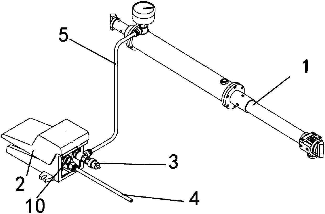
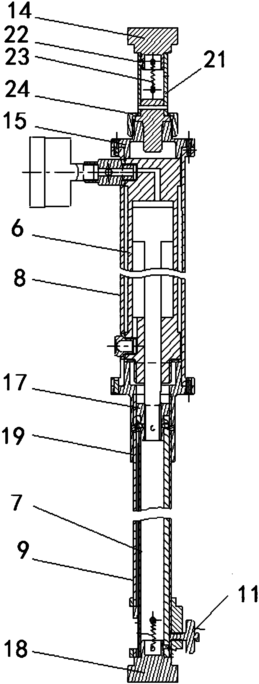
The invention discloses a loading measurement system for measuring the inner diameter of the adjustable nozzle of an engine and belongs to the technical field of engine measurement. The loading measurement system comprises that an air source is connected to the air inlet end of a foot switch via an air inlet hose, the air outlet end of the foot switch is connected to a constant-pressure valve andan air supply hose connected to a measuring device through a three-way pipe; a first test anvil is disposed on a long rod assembly which is connected with a first outer sleeve through a first conversion base, the first outer sleeve is equipped with a pressure gauge; an air pressure actuator is arranged in the first outer sleeve; a measuring rod is connected with the tail end of the piston rod of the air pressure actuator via an adaptor; when the air source communicates with the air pressure actuator, the piston rod of the air pressure actuator drives the measuring rod to move along a second outer sleeve; when a second test anvil of the measuring rod is in contact with a nozzle measuring surface, a pressure value increases, when pressure value reaches a specified value, the constant-pressure valve automatically releases pressure to maintain the set expansion force, a locking device is locked, and the scale is read when a fixed scale is aligned with the scale of the measuring rod.

Description

technical field [0001] The invention belongs to the technical field of engine measurement, in particular to a loading measurement device for measuring the inner diameter of an adjustable nozzle of an engine. Background technique [0002] After the nozzle assembly of the aero-engine is completed, the actual nozzle diameter needs to be measured to check compliance with the design requirements; after the engine is installed on the aircraft or the nozzle angular displacement sensor is replaced, the actual nozzle diameter needs to be measured to calibrate the control system. After the adjustable nozzle is assembled, each component part has a certain contraction effect on the nozzle under the action of gravity. The diameter of the nozzle controlled by the actual engine working state is the diameter of the nozzle after bearing the outward expansion force of the exhaust gas. Therefore, the measuring device used should be used for measurement. A certain amount of tension can be appli...

Claims


Application Information

Patent Timeline
IPC IPC(8): G01B5/12
CPCG01B5/003G01B5/12
Inventor 王其福吕天波种强张生王维岩刘君范顺昌齐晓辉
Owner AECC SHENYANG ENGINE RES INST
Learn More