A high-efficiency drying machine
What is Al technical title?
Al technical title is built by PatSnap Al team. It summarizes the technical point description of the patent document.
A trigger and high-efficiency technology, applied in the field of exposure equipment for contact printing, can solve the problems of low drying efficiency and poor uniformity of the photosensitive plate, and achieve the effect of avoiding the emission of harmful gases, improving processing efficiency and ensuring health.
Inactive Publication Date: 2020-04-14
启东市启秀蔬果专业合作社
View PDF6 Cites 0 Cited by
Summary
Abstract
Description
Claims
Application Information
AI Technical Summary
This helps you quickly interpret patents by identifying the three key elements:
Problems solved by technology
Method used
Benefits of technology
Problems solved by technology
[0005] Although the above-mentioned scheme can realize the conventional drying board operation, it still has the following problems: 1. When drying boards, only one board can be dried at a time, and the efficiency of drying boards is low; 2. The light source used for drying boards is drying During the plate process, the uniformity of the photosensitive plate is not good
Method used
Image
Click on the blue label to locate the original text in one second.
Reading with bidirectional positioning of images and text.
Examples
Embodiment 2
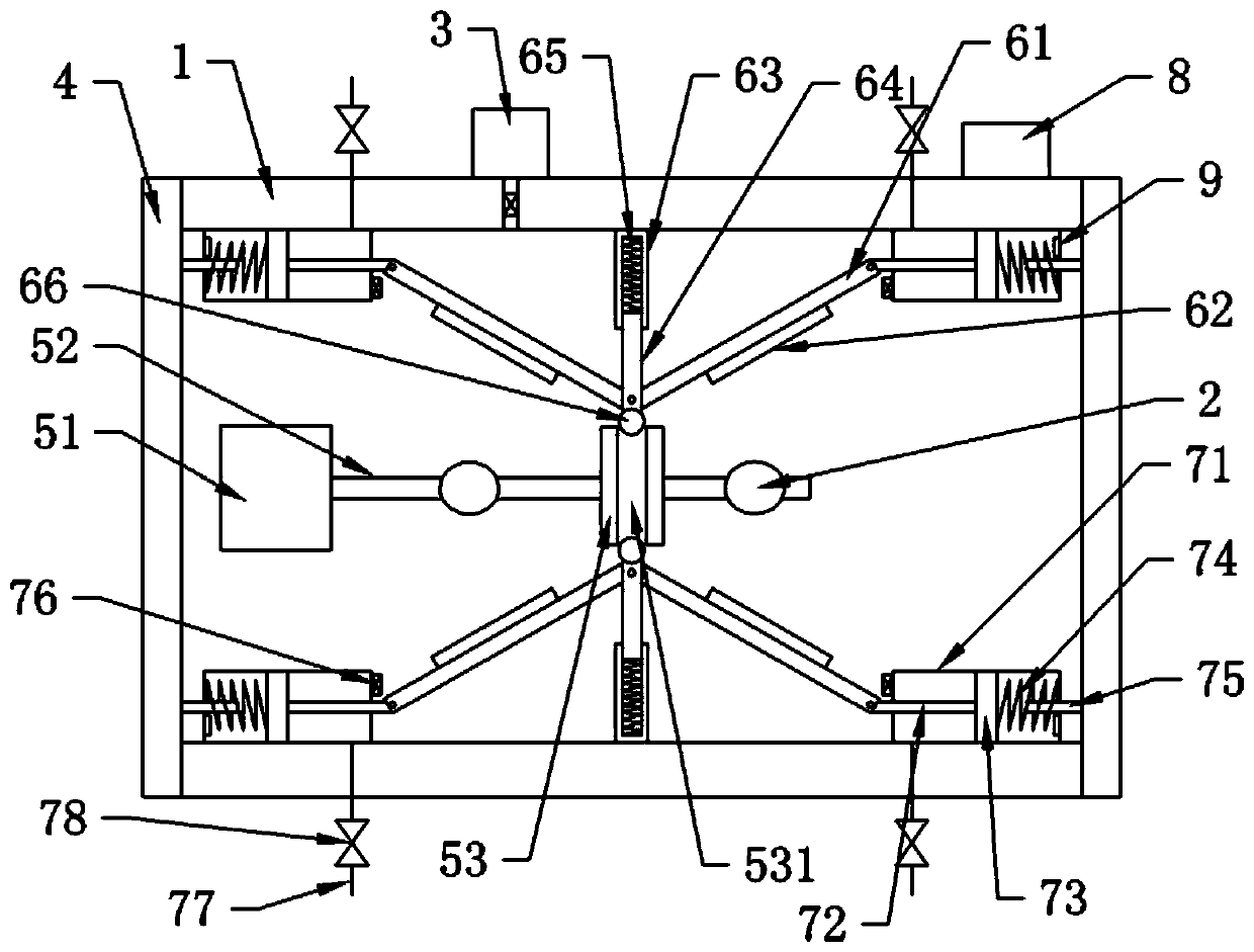
[0033] Such as figure 2 As shown, the difference between this embodiment and embodiment 1 is that the control unit also includes a controller 8 and a pressure sensor 9. The controller 8 can be a MAM-200 controller purchased on the market, and the pressure sensor 9 can be purchased on the market. PT124G-213 pressure sensor, the pressure sensor 9 is arranged at the bottom of the gas cylinder 71 away from the push rod 72, the valve 78 is an electric control valve, and the electric control valve and the pressure sensor 9 are electrically connected to the controller 8 respectively.
[0034] In this solution, as the rotating wheel 53 rotates, gas is continuously sucked in the air reservoir 71 until the piston body 73 abuts against the pressure sensor 9 and squeezes, when the pressure received by the pressure sensor 9 reaches the upper limit set by the controller 8. After the value, the controller 8 controls the electric control valve to open, thereby expelling the gas in the gas cylin...
PUM
Abstract
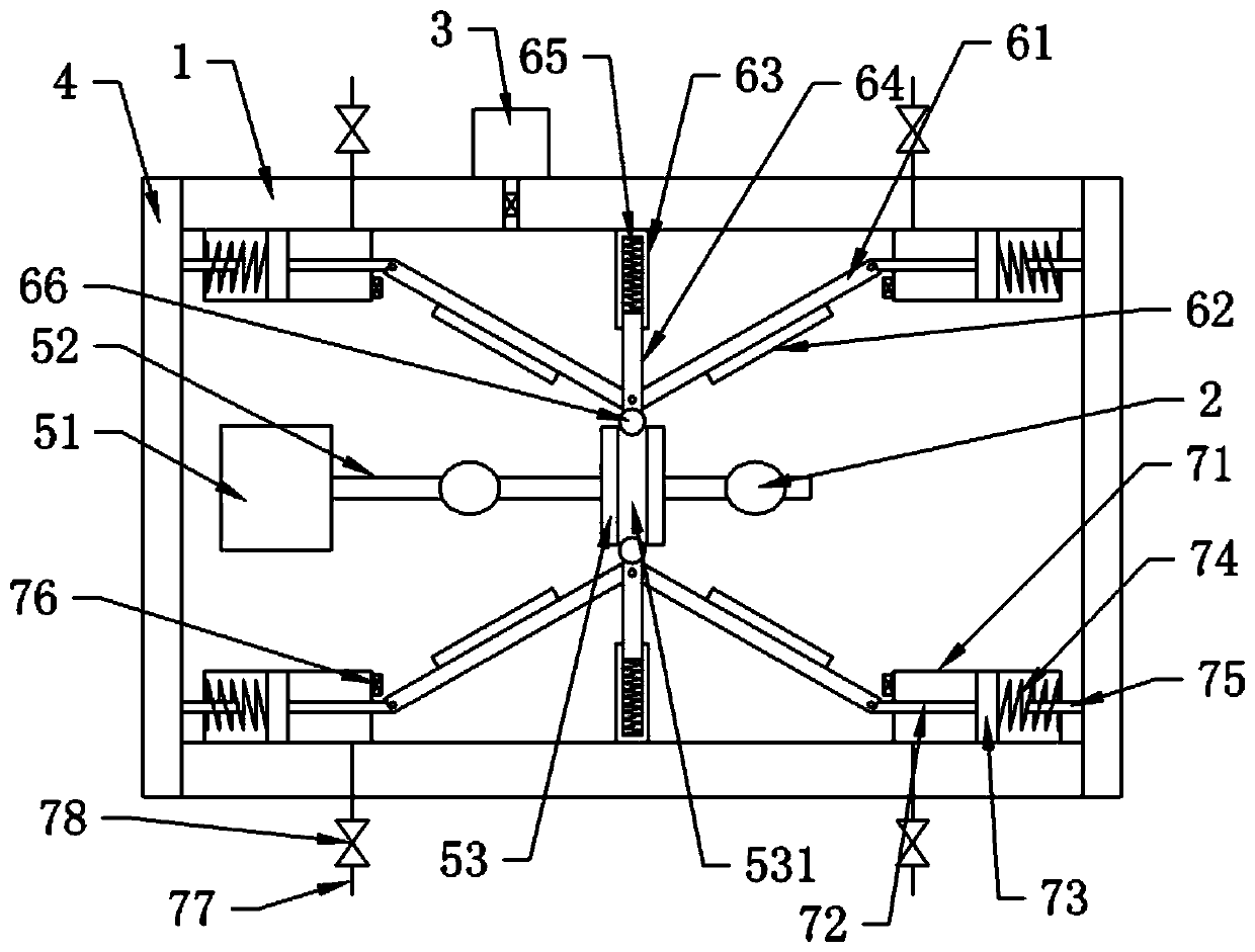
The invention discloses an efficient printing down machine. The efficient printing down machine comprises a machine box, ultraviolet lamps, a vacuum pump, a drive part, a printing down part and a control part and is characterized in that the air pumping port of the vacuum pump is communicated with the lower portion of the machine box through a pipeline, and the machine box is provided with a sealing cover; the drive part comprises a rotary shaft, a rotary wheel and a power source for driving the rotary shaft to rotate, the rotary wheel is connected to the rotary shaft, and the circumferentialface of the rotary wheel is provided with a cam groove; the printing down part comprises four rotary racks, four printing down units, slide seats and slide rods, one printing down unit is mounted on each rotary rack, the slide seats and the slide rods are oppositely arranged on the opposite lateral walls of the machine box, and the ultraviolet lamps opposite to the printing down units are arrangedon the rotary shaft; the control part is mounted at a position, close to the sealing cover, of the machine box and comprises an air storage cylinder, a push rod, a piston and ejector pin, the pistonis slidably connected into the air storage cylinder, one side, close to the push rod, of the air storage cylinder is provided with an exhaust pipe, and the exhaust pipe is provided with a valve. The efficient printing down machine has the advantages that printing down of multiple plates in one step can be achieved, high processing efficiency is achieved, and printing down uniformity can be guaranteed.
Description
Technical field [0001] The invention relates to an exposure equipment for contact printing, in particular to a high-efficiency exposure machine. Background technique [0002] Exposure machine is commonly known as (photosensitive seal engraving machine, portrait seal machine, wedding seal engraving machine). As the latest type of seal in the world, the photosensitive seal is simple and quick to produce, clear seal, long service life, and strong applicability. Promote and become an upgraded product of my country's seal industry. [0003] The exposure machine irradiates the ultraviolet light emitted from the ultraviolet lamp tube through the film to the photosensitive plate, so that the light-transmitting part of the corresponding film on the photosensitive plate produces a photochemical reaction to generate water-insoluble polymer chains. After the plate is washed, this part is left as a raised part, thereby forming the required pattern on the photosensitive plate. [0004] The patent...
Claims
Application Information
Patent Timeline
Application Date:The date an application was filed.
Publication Date:The date a patent or application was officially published.
First Publication Date:The earliest publication date of a patent with the same application number.
Issue Date:Publication date of the patent grant document.
PCT Entry Date:The Entry date of PCT National Phase.
Estimated Expiry Date:The statutory expiry date of a patent right according to the Patent Law, and it is the longest term of protection that the patent right can achieve without the termination of the patent right due to other reasons(Term extension factor has been taken into account ).
Invalid Date:Actual expiry date is based on effective date or publication date of legal transaction data of invalid patent.