Sliding torque-changing motor

A technology of variable torque motors and motor housings, applied in the direction of electrical components, electromechanical devices, etc., which can solve problems such as difficulty in grasping, increased maintenance, noise, and damage to electronic control systems, and achieves stable installation and reduced energy loss.

Pending Publication Date: 2018-05-18
WERNERFUJIAN POWER CO LTD
View PDF0 Cites 1 Cited by
  • Summary
  • Abstract
  • Description
  • Claims
  • Application Information

AI Technical Summary

Problems solved by technology

[0002] Existing motors and engines, such as motors for automobiles and ships, are the reason for the power change output during operation. The speed and torque are usually in a nonlinear relationship, and high speed and high torque cannot be achieved at the same time. Insufficient power, unable to meet the requirements of use, and when a car needs a high torque when passing a pit or climbing a slope, because the high torque output of the car is not at a high speed moment, it is difficult to grasp when the high torque output can be obtained, and the control is difficult Generators such as wind power generators, in order to output constant frequency electric energy under different wind speeds, usually use double-fed asynchronous generators. The rotor winding of the generator is con

Method used


Image

  • Sliding torque-changing motor
  • Sliding torque-changing motor
  • Sliding torque-changing motor

Examples


Embodiment Construction

[0020] The preferred embodiments of the sliding torque converter motor of the present invention will be described in detail below with reference to the accompanying drawings.

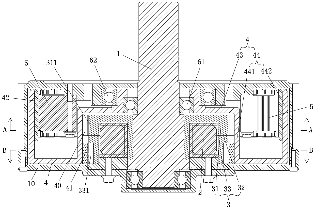
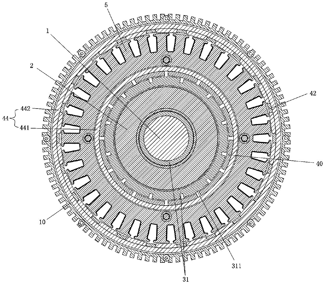
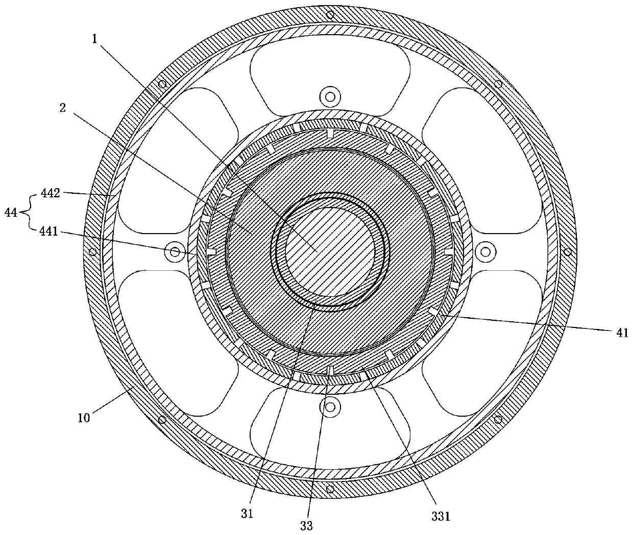
[0021] Such as Figure 1 to Figure 3 As shown, a sliding torque motor includes a motor housing 10 and a motor shaft 1 passing through the motor housing 10. The motor housing 10 is provided with a magnetic pole coil 2 fixedly connected to the motor shaft. 1 is the center winding, the motor shaft 1 is inherently set with a magnetic pole rotor 3 coaxial with the magnetic pole coil 2. The magnetic pole rotor 3 includes the first magnetically conductive ring segments 31, which are located outside the magnetic pole coil 2 and are sequentially connected and distributed along the axial direction. The magnetic ring segment 32 and the second magnetic permeable ring segment 33. The outer periphery of the first magnetic permeable ring segment 31 extends radially outward along the shaft with a number of first protrusio...


PUM


Abstract

The invention discloses a sliding torque-changing motor, comprising a motor casing and a motor rotating shaft passing through the motor casing. The motor casing is internally provided with a pole coilfixedly connected thereto, and the motor rotating shaft is sleeved and fixed with a pole rotor coaxial with the pole coil. The pole rotor includes a first magnetic conductive ring segment, a non-magnetic conductive segment and a second magnetic conductive ring segment located outside the pole coil and axially connected and distributed, a plurality of first bumps and second bumps extend outwards in the axial and radial direction along the outer periphery of the first magnetic conductive ring segment and the second magnetic conductive ring segment, and a rotor and a stator winding are coaxiallyarranged outside the pole rotor. A first adjustable flux magnetic steel and a second adjustable flux magnetic steel are fixed on the inner wall of the rotor, a rotor magnetic steel is also provided on the rotor, and the stator winding is fixedly connected with the motor casing. The sliding torque-changing motor can be used as a motor, and can also be used as a generator. When used as an engine, the output rotating speed and the torque are adjustable. When used as a generator, the current, voltage and frequency of the output electrical signal are adjustable, and the adjustment is simple and the application range is wide.

Description

Technical field [0001] The invention relates to the field of motors, in particular to a sliding torque converter motor. Background technique [0002] Existing motors, such as motors for automobiles and ships, are the reasons for the power output during operation. The speed and torque are usually in a non-linear relationship. High speed and large torque cannot be achieved at the same time. It appears in some operating conditions or applications. It is inadequate and cannot meet the requirements of use, and when the car needs a large torque when going through a pit or climbing a slope, because the car outputs a large torque not at a high speed, it is difficult to grasp when the large torque output can be obtained, and the control is difficult ; Generators such as wind turbines, in order to still output constant frequency electric energy at different wind speeds, usually double-fed asynchronous generators, doubly-fed pilot step generators are equipped with power converters, doubly-f...

Claims


Application Information

Patent Timeline
IPC IPC(8): H02K16/02
CPCH02K16/02
Inventor 张雄峰
Owner WERNERFUJIAN POWER CO LTD
Why Eureka
Try Eureka