Flat panel detector gain correction template updating method

A flat-panel detector and gain correction technology, which is applied in the fields of radiological diagnosis instruments, medical science, diagnosis, etc. Work efficiency and other issues, to achieve the effect of simple update methods and steps, reducing pre-exposure time and improving work efficiency

Active Publication Date: 2018-05-22
SHANGHAI IRAY TECH
View PDF7 Cites 8 Cited by
  • Summary
  • Abstract
  • Description
  • Claims
  • Application Information

AI Technical Summary

Problems solved by technology

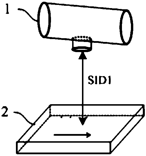
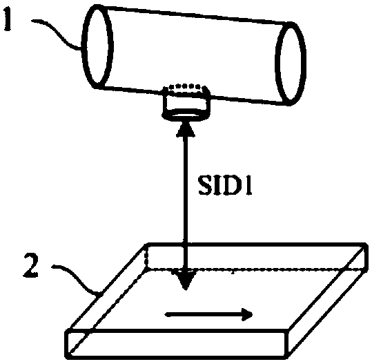
[0004] Currently, in Gain correction, it is necessary to generate a static gain correction template, and the template is time-sensitive. When the spatial information or physical information between the detector and the tube changes, there is a problem of frequent updating: the first reason is , the X-ray ray diverges in the direction of the detector in a cone shape after being emitted from the tube, and only the center line has the highest intensity, and the intensity gradually decreases as it moves away from the center ray; the second reason is that as the focus of the tube and the detector As the distance of the incident surface increases (SID increases), the intensity of the X-ray rays reaching the detector incident surface gradually decreases, and the divergence degree of the X-ray rays and the difference in the intensity of the X-ray rays between the center and the periphery also decrease. The third reason is that the X-ray ray is emitted from the anode target of the ball tube to the detector. Because the anode has a certain target angle, the radiation dose at the cathode end of the ball tube is relatively high, while the radiation dose at the anode end gradually decreases.
However, to update the gain correction file, it is necessary to take a certain number of bright-field images (usually five or more empty-field images without any objects) at a specific dose, which has certain restrictions, which increases the number of operators. The work preparation time, workload and work difficulty also affect the customer experience, increase the waiting time for irradiated objects, and reduce work efficiency

Method used


Image

  • Flat panel detector gain correction template updating method
  • Flat panel detector gain correction template updating method
  • Flat panel detector gain correction template updating method

Examples


Embodiment Construction

[0042] Embodiments of the present invention are described below through specific examples, and those skilled in the art can easily understand other advantages and effects of the present invention from the content disclosed in this specification. The present invention can also be implemented or applied through other different specific implementation modes, and various modifications or changes can be made to the details in this specification based on different viewpoints and applications without departing from the spirit of the present invention. It should be noted that, in the case of no conflict, the following embodiments and features in the embodiments can be combined with each other.

[0043] It should be noted that the diagrams provided in the following embodiments are only schematically illustrating the basic ideas of the present invention, although only the components related to the present invention are shown in the diagrams rather than the number, shape and shape of the ...


PUM


Abstract

The invention provides a flat panel detector gain correction template updating method. When the flat panel detector is moved to any to-be-corrected position, image gain correction coefficient in the position state can be calculated through a frame of a to-be-processed jejunum image and by combining with an acquired image gain correction file, so that image heterogeneity due to X-ray can be accurately corrected without needing to photograph a large number of reference images of different doses again; pre-exposure time of operators and operation difficulty are reduced, technical training periodis shortened, real-time performance is strong, the images can be used instantly after the images are photographed, waiting time of patients is synchronously reduced, working efficiency is improved, and the updating method and steps are simple, so that mobility and convenience of the flat panel detector are further enhanced.

Description

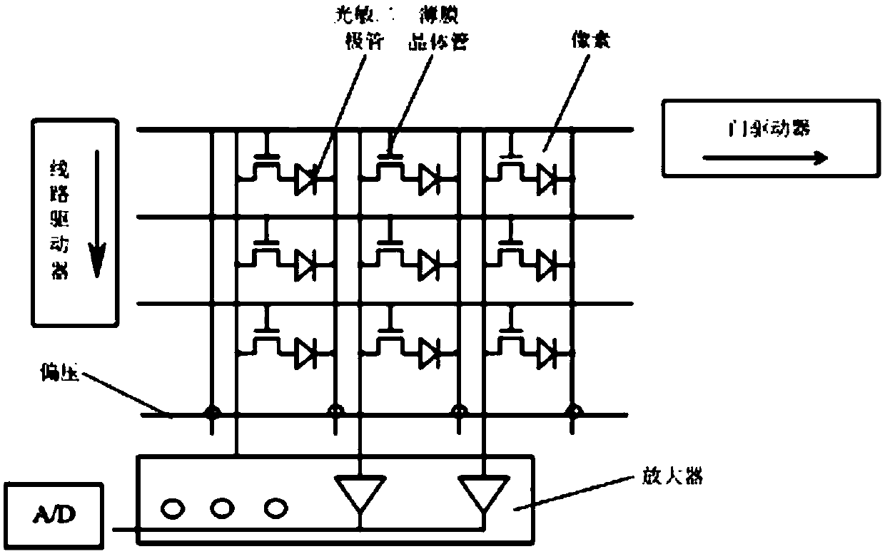
technical field [0001] The invention belongs to the technical field of flat panel detector physics, in particular to a method for updating a gain correction template of a flat panel detector. Background technique [0002] The X-ray flat panel detector is composed of a large number of pixels with relative coordinate positions. Each pixel is an X-ray detection unit, which accurately quantifies the amount of X-ray rays to form good image information. An ideal flat-panel detector should have pixels with consistent detection characteristics, but in practice, it is impossible for each pixel of each flat-panel detector to achieve completely consistent detection characteristic quality. In order to maximize the measurement range of each pixel, the measurement accuracy of each pixel must be calibrated. The normalized calibration of the background is called Offset correction, and the normalized calibration of the gain is called Gain correction. [0003] The inhomogeneity of the image ...

Claims


Application Information

Patent Timeline
Patent Type & Authority Applications(China)
IPC IPC(8): A61B6/00
CPCA61B6/4208A61B6/44A61B6/585
Inventor 王锋张楠金利波
Owner SHANGHAI IRAY TECH
Why Eureka
Try Eureka