Die stamping device with turnover workbench

A stamping device and workbench technology, which is applied to stamping machines, manufacturing tools, presses, etc., can solve the problems of labor consumption and low work efficiency, and achieve the effects of saving labor, improving work efficiency, and reasonable and applicable structural design

Inactive Publication Date: 2018-05-22
ZHENGZHOU MOORE ELECTRONICS INFORMATION TECH CO LTD
View PDF7 Cites 27 Cited by
  • Summary
  • Abstract
  • Description
  • Claims
  • Application Information

AI Technical Summary

Problems solved by technology

[0004] At present, most of the existing stamping devices need to take the workpiece manually...

Method used


Image

  • Die stamping device with turnover workbench
  • Die stamping device with turnover workbench

Examples


Embodiment Construction

[0018] The following will clearly and completely describe the technical solutions in the embodiments of the present invention with reference to the accompanying drawings in the embodiments of the present invention. Obviously, the described embodiments are only some, not all, embodiments of the present invention. Based on the embodiments of the present invention, all other embodiments obtained by persons of ordinary skill in the art without making creative efforts belong to the protection scope of the present invention.

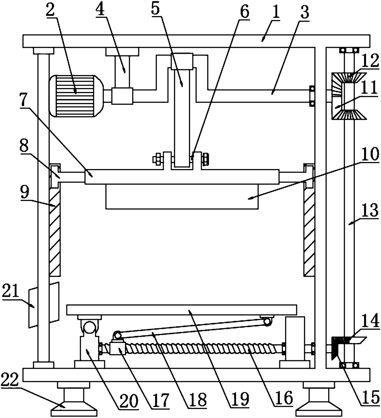
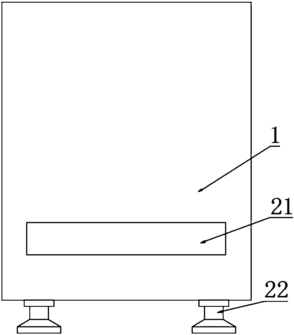
[0019] see Figure 1~2 , in an embodiment of the present invention, a die stamping device with a reversible workbench includes a device body 1; , a screw rod 16 and a connecting rod 18; the upper left end of the device body 1 is fixedly connected to the drive motor 2, the drive motor 2 is electrically connected to the power supply and the switch, the right side of the drive motor 2 is connected to the crankshaft 3, and the left side of the crankshaft 3 is conn...


PUM


Abstract

The invention discloses a die stamping device with a turnover workbench. According to the die stamping device, a driving motor is fixedly connected to the upper part of the left end of a device body;a crankshaft is connected to the right side of the driving motor in a rotating mode; the left side of the crankshaft is sleeved with the lower end of a lifting rod; the upper end of the lifting rod isfixedly connected to the device body; a bearing on the right side of the crankshaft is connected to the device body in a rotating mode; the middle of the crankshaft is sleeved with the upper end of apush rod; the lower end of the push rod is connected to the middle of a pin shaft in a rotating mode; the two ends of the pin shaft are connected to the upper ends of a transverse plate in a rotatingmode; the lower end of the transverse plate is fixedly connected to a stamping die; the right end of the crankshaft is fixedly connected to a first semi-bevel gear; and two first bevel gears are arranged at the upper part and the lower part of the first semi-bevel gear. According to the die stamping device, the transverse plate is driven to move up and down along guide grooves in a reciprocatingmode through the crankshaft so as to drive the stamping die to move up and down to complete the stamping action, meanwhile, the second bevel gear which intermittently rotates forwards and reversely ina reciprocating mode drives a screw to intermittently rotate forwards and reversely in a reciprocating mode so as to drive the workbench to preform intermittent swing discharging through a connectingrod. The die stamping device has the advantages of being reasonable and practical in structural design and capable of realizing automatic discharging and saving the labor force.

Description

technical field [0001] The invention relates to a mold processing machine, in particular to a mold stamping device with a reversible workbench. Background technique [0002] Punching machine is a stamping press. In national production, the stamping process saves materials and energy compared with traditional machining, has high efficiency, does not require high technical requirements for operators, and can be machined through various mold applications. These advantages of products that cannot be achieved, so its use is becoming more and more extensive. [0003] Stamping production is mainly for plates. Through the mold, blanking, punching, forming, deep drawing, trimming, fine blanking, shaping, riveting and extrusion parts can be made, which are widely used in various fields. For example, we use switch sockets, cups, cupboards, dishes, computer cases, and even missile aircraft... There are many accessories that can be produced by punching through molds. [0004] At prese...

Claims


Application Information

Patent Timeline
IPC IPC(8): B30B1/14B30B15/32B21D22/02B21D45/02
CPCB30B1/14B21D22/02B21D45/02B30B15/32
Inventor 邢济祥
Owner ZHENGZHOU MOORE ELECTRONICS INFORMATION TECH CO LTD
Why Eureka
Try Eureka