Electromagnetic shaftless reverse type centripetal vortex-blade hydroelectric generator

A hydraulic generator, reverse type technology, applied in the direction of engine components, machines/engines, electrical components, etc., can solve the problems of unreasonable hydraulic machine structure, less contact time between water body and blade, and small acceleration force, so as to improve hydraulic power The effects of increased power generation capacity, reservoir power generation, and increased working hours

Inactive Publication Date: 2018-05-22
汪弘轩
View PDF6 Cites 0 Cited by
  • Summary
  • Abstract
  • Description
  • Claims
  • Application Information

AI Technical Summary

Problems solved by technology

[0003] To sum up, the problems existing in the existing technology are: the traditional hydraulic machine is separated from the generator body, the single blade of the hydraulic machine belongs to short-stroke work, the contact time between the water body and the blade is small, the acceleration force is small, and the continuous work cannot be performed, and the impact force between the blade and the water body Large, large water consumption, low power generation, low working efficiency, low power generation, high noise, waste of water resources and other disadvantages in use, the key lies in the unreasonable structure of the hydraulic machine

Method used


Image

  • Electromagnetic shaftless reverse type centripetal vortex-blade hydroelectric generator
  • Electromagnetic shaftless reverse type centripetal vortex-blade hydroelectric generator

Examples


Embodiment Construction

[0031] In order to make the object, technical solution and advantages of the present invention more clear, the present invention will be further described in detail below in conjunction with the examples. It should be understood that the specific embodiments described here are only used to explain the present invention, not to limit the present invention.

[0032] The application principle of the present invention will be further described below in conjunction with the accompanying drawings and specific embodiments.

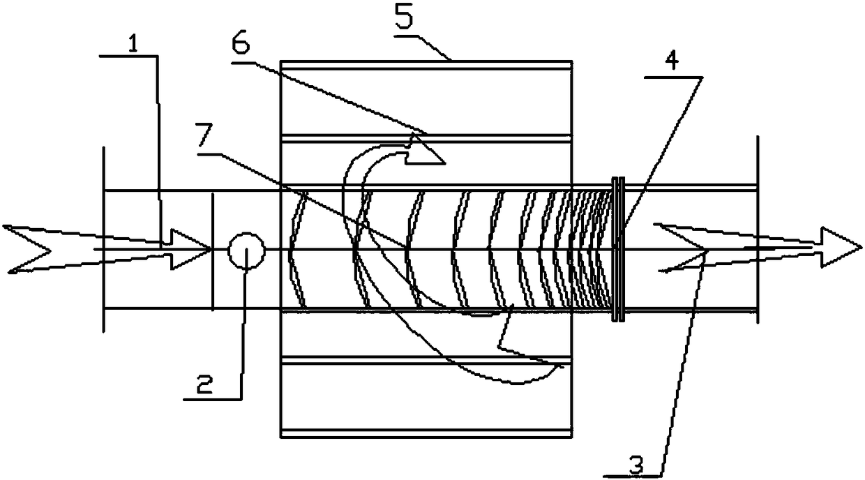
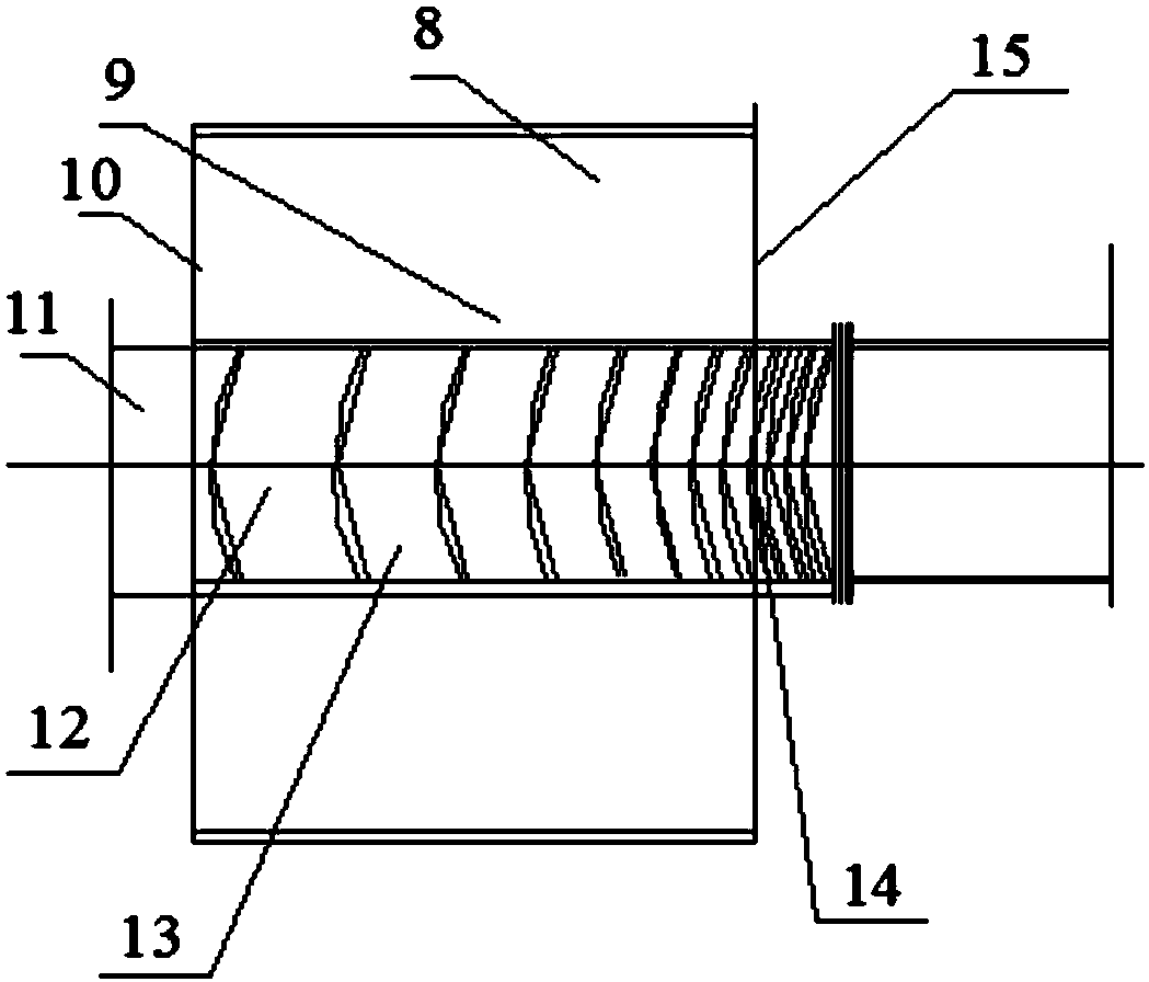
[0033] Such as Figure 1 to Figure 2 As shown, the electromagnetic shaftless reverse type centripetal vortex hydroelectric generator provided by the embodiment of the present invention is provided with a hydraulic machine rotating cylinder 10, and the inside of the hydraulic machine rotating cylinder 10 is provided with periodically surrounding reverse The centripetal continuous strip-shaped vortex blade passage 13, the radial outer edge of the centripetal conti...


PUM


Abstract

The invention belongs to the technical field of reverse type centripetal hydroelectric generation devices which are high in rotating force and low in noise, and discloses an electromagnetic shaftlessreverse type centripetal vortex-blade hydroelectric generator. The electromagnetic shaftless reverse type centripetal vortex-blade hydroelectric generator is provided with a generator body and a hydraulic machine rotary cylinder which are integrated. A reverse type centripetal continuous long strip-shaped shaftless vortex blade channel which zigzags periodically is formed in the hydraulic machinerotary cylinder. The radius of the outer edge of a continuous long strip-shaped shaftless vortex blade is unchanged, the inclination angle of the blade is gradually changed topologically from 45 degrees to 90 degrees, the screw pitch of the blade is increased gradually, and the space of the continuous long strip-shaped shaftless vortex blade channel is gradually increased. By adoption of the electromagnetic shaftless reverse type centripetal vortex-blade hydroelectric generator, the defects that a centrifugal impeller unit of a traditional hydraulic machine is sheet, cannot work continuously and is small in acceleration force, the impact force between a blade and a water body is large, the resistance is large, the noise is high, and the generation power is low are overcome; and the electromagnetic shaftless reverse type centripetal vortex-blade hydroelectric generator has the advantages of extremely high rotating force, high power generation capacity, low noise, safety, stable operating, compact and reasonable structure, remote control and the like.

Description

technical field [0001] The invention belongs to the technical field of super-strong rotation force, super-power generation, low noise, electromagnetic shaftless reverse type centripetal vortex hydraulic machine and generator device, and particularly relates to an electromagnetic shaftless reverse type Heart type vortex hydroelectric generator. Background technique [0002] At present, the traditional hydraulic generators at home and abroad are separated from the generator and the hydraulic machine. Most of the impellers of the hydraulic machine are single-blade short-stroke centrifugal type working in series. , high water consumption, waste of water resources and other disadvantages. Many countries at home and abroad have invested a lot of manpower and financial resources in research, hoping to increase the contact time between the water body and the blades and increase the acceleration of the water body movement, so that the hydroelectric generator can save water resources...

Claims


Application Information

Patent Timeline
Patent Type & Authority Applications(China)
IPC IPC(8): F03B13/00H02K7/18
CPCF03B13/00H02K7/1823
Inventor 汪弘轩汪一平
Owner 汪弘轩
Why Eureka
Try Eureka