
Rotary drum drainage mechanism of horizontal spiral centrifuge

A horizontal screw and centrifuge technology, applied in the field of centrifuges, can solve the problem of inability to separate two-phase mixed materials, and achieve the effects of simple structure, simple and reliable structure, and stable and reliable function.

Pending Publication Date: 2018-05-25
南京达旻机械制造有限公司
View PDF0 Cites 3 Cited by
  • Summary
  • Abstract
  • Description
  • Claims
  • Application Information

AI Technical Summary

Problems solved by technology

[0003] In order to solve the existing horizontal screw centrifuge existing in the prior art, the solid phase density ρ cannot be separated

Method used


Image

  • Rotary drum drainage mechanism of horizontal spiral centrifuge
  • Rotary drum drainage mechanism of horizontal spiral centrifuge
  • Rotary drum drainage mechanism of horizontal spiral centrifuge

Examples


Embodiment

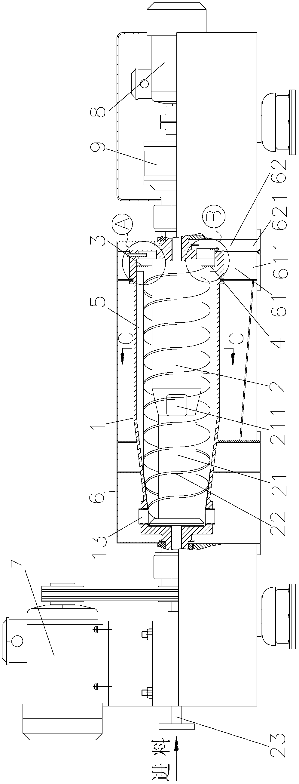
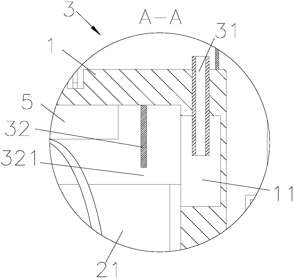
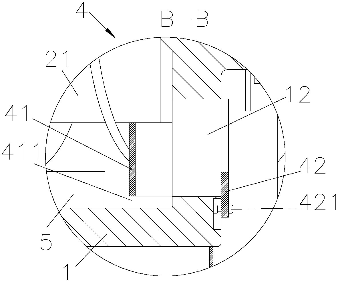
[0022] like Figure 1~4 As shown, a drum draining mechanism of a horizontal screw centrifuge is characterized in that it includes a cover 6, a drum 1 rotatably arranged in the cover 6 and a screw unloader rotatably arranged in the drum 1 2. One end of the drum 1 is driven to rotate by the main motor 7. The screw unloader 2 includes a hollow mandrel 21 and a screw pusher blade 22 arranged on the mandrel 21. The mandrel 21 is located on the other side of the drum 1. One end of one end is fixedly connected with the differential gear 9, and the differential gear 9 is driven by the auxiliary motor 8, and one end of the inner cavity of the mandrel 21 is provided with a feed pipe 23, and the mandrel 21 is provided with a The inner chamber of the drum 1 is connected to the feed port 211, and the mandrel 21 is provided with an accelerator with a distribution chamber, and the distribution chamber is respectively connected with the feed pipe 23 and the feed port 211. port 13, the other ...


PUM


Abstract

The invention belongs to the technical field of centrifugal machines, and particularly relates to a rotary drum drainage mechanism of a horizontal spiral centrifuge. The rotary drum drainage mechanismcomprises a rotating drum, a spiral discharger and a liquid discharging device 1, wherein a slag discharging opening is formed in one end of the rotary drum in a penetrating manner; the spiral discharger is rotationally arranged in the rotary drum, wherein the spiral discharger comprises a hollow core shaft and spiral pushing blades which is arranged in the core shaft; a liquid discharging deviceI is arranged at the other end of the rotary drum, wherein the liquid discharging device I comprises a baffle I and an overflow structure I which are arranged in sequence; and the top end of the baffle I is cooperated with the core shaft, and the bottom end of the baffle I is fixed on the rotary drum and a channel I is formed between the top end of the baffle I and the inner wall of the rotary drum; and the overflow structure I is communicated with the inner cavity of the rotary drum through the channel I and is used for discharging heavy liquid in the rotary drum. The rotary drum liquid discharge mechanism of the horizontal spiral centrifuge has the beneficial effects that separation from the three-phase mixed material with light liquid phase density rho light liquid smaller than the solid-phase density rho-solid and smaller than the heavy liquid phase density rho heavy liquid; and the structure is simple and firm, and the cost is low.

Description

technical field [0001] The invention belongs to the technical field of centrifuges, in particular to a drum draining mechanism of a horizontal screw centrifuge. Background technique [0002] The horizontal screw centrifuge uses the principle of obtaining different sedimentation velocities in the centrifugal force field by using the light, heavy liquid and solid phases with different densities and immiscibility in the mixed liquid to achieve separation and stratification or to settle the solid particles in the liquid the goal of. During the process of centrifuge separating materials, the solid phase particles move to the discharge port at the small end, while the light phase (liquid) flows through the spiral channel to the liquid phase exit at the large end to be discharged out of the machine. Existing horizontal screw centrifuges can only separate mixed materials with solid phase density ρsolid>liquid phase density ρliquid, or can only separate solid phase density ρsolid...

Claims


Application Information

Patent Timeline
IPC IPC(8): B04B1/20B04B11/02B04B15/06
CPCB04B1/20B04B11/02B04B15/06
Inventor 宋立华李哲璐宋晓君
Owner 南京达旻机械制造有限公司
Learn More