
Manufacturing and installing process for hydraulic movable hanging bracket

A technology of mobile hanger and installation process, which is applied in hoisting devices, portable lifting devices, etc., and can solve the problems of single production, inability to guarantee product quality requirements and product functions, etc.

Inactive Publication Date: 2018-05-25
QINGDAO CENTURY YUNFAN IND
View PDF0 Cites 0 Cited by
  • Summary
  • Abstract
  • Description
  • Claims
  • Application Information

AI Technical Summary

Problems solved by technology

[0002] Each product has its unique production and processing methods, and the different structures and materials of the product will also have a very different installation process from other products. According to the characteristics of the product, a more complete and most suitable production and installation process can be made. There are fewer detours in the production and installation process, and at the same time, it can save manpower, material resources and raw materials, and produce high-quality and low-cost products safely and quickly. The hydraulic movable hanger is a non-standard product, so the production of the product is single. This determines that the production and manufacture of components must have its special manufacturing process, otherwise the quality requirements and functions of the product cannot be guaranteed

Method used


Image

  • Manufacturing and installing process for hydraulic movable hanging bracket
  • Manufacturing and installing process for hydraulic movable hanging bracket

Examples


Embodiment Construction

[0009] The present invention will be further described below in conjunction with accompanying drawing.

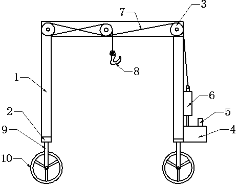
[0010] Take the hydraulic movable hanger as an example, weld the portal frame 1 with channel steel—weld the wheel frame 2 at both ends of the bottom of the portal frame 1, install the vertical wheel shaft 9, and the walking wheel 10—install at the lower right end of the portal frame 1 Hydraulic oil tank 4 with hydraulic oil pump 5—the hydraulic oil pump 5 is connected to the hydraulic oil cylinder 6 at the upper end of the hydraulic oil tank 4 with an oil pipe—three oil wire rope sheaves 3 are installed side by side on the top of the portal frame 1, and the oil wire rope 7 is connected - The hook 8 is installed on the upper end of the oil wire rope 7, and the lower end is connected and fixed to the hydraulic cylinder 6 - The overall surface is polished, polished, and painted - The installation part and appearance inspection - Functional test: connect the power supply of the ...


PUM


Abstract

The invention discloses a manufacturing and installing process for a hydraulic movable hanging bracket. The manufacturing and installing process comprises the following steps that a portal frame is welded by channel steel; wheel frames are welded to two ends of frame bottoms of the portal frame, and vertical wheel shafts and road wheels are installed on the wheel frames; a hydraulic oil tank witha hydraulic oil pump is installed at the right lower end of the portal frame; the hydraulic oil pump is connected with a hydraulic oil cylinder on the upper end of the oil tank through an oil pipe; three oil wire rope groove wheels are installed on the top end of the portal frame side by side, and an oil wire rope is hung on the oil wire rope groove wheels; a lifting hook is installed at the upperend of the oil wire rope, the lower end of the oil wire rope is fixedly connected with the upper part of the hydraulic oil cylinder; the whole surface is subjected to grinding, polishing and paint spraying; installed parts and the appearance are inspected; and a function test is carried out. According to the manufacturing and installing process for the hydraulic movable hanging bracket, orderly production and installation can be carried out according to specifications, so that the manufacturing quality and requirements of products are guaranteed, irrelevant and unnecessary links are reduced,meanwhile, raw materials can be saved, cost can be reduced, and the machining and installing process follows rules, and is safe and orderly.

Description

technical field [0001] The invention relates to a manufacturing and installation process of a hydraulic movable hanger, which is a process for hoisting and hoisting heavy parts equipment for outdoor maintenance of equipment and various machines. Background technique [0002] Each product has its unique production and processing methods, and the different structures and materials of the product will also have a very different installation process from other products. According to the characteristics of the product, a more complete and most suitable production and installation process can be made. There are fewer detours in the production and installation process, and at the same time, it can save manpower, material resources and raw materials, and produce high-quality and low-cost products safely and quickly. The hydraulic movable hanger is a non-standard product, so the production of the product is single. This determines that the production and manufacture of components mus...

Claims


Application Information

Patent Timeline
IPC IPC(8): B66D3/20B66D3/26
CPCB66D3/20B66D3/26
Inventor 赵岳鹏
Owner QINGDAO CENTURY YUNFAN IND
Learn More