

Ringlike quenching device and application method thereof
The technology of a quenching device and an application method is applied in the field of steel pipe quenching, which can solve the problems of large investment and low return rate, and achieve the effects of simple and quick adjustment of the nozzle angle, labor reduction, and easy installation.
- Summary
- Abstract
- Description
- Claims
- Application Information
AI Technical Summary
Problems solved by technology
Method used
Image

Examples
Embodiment 1
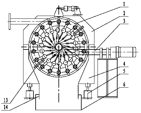
[0027] The present invention provides such figure 1 and figure 2 An annular quenching device is shown, including a water spray ring 1, a frame 4 and a conveying roller table 3, the water spray ring 1 is vertically installed on the frame 4, and the conveying roller table 3 is placed perpendicular to the central axis of the water spray ring 1 ground, and the conveying roller table 3 is located below the central axis of the water spray ring 1.
[0028] The working process of the ring quenching device is as follows:
[0029] Multiple groups of water spray rings 1 are installed in a straight line on the frame 4, and the steel pipes are driven by the conveying roller table 3 to rotate and pass through the water spray rings 1 forward, and the water sprayed by the water spray rings 1 is sprayed onto the outer surface of the steel pipes in a tangential direction. Guarantee the cooling speed of the steel pipe to ensure that the quenched martensite structure is obtained until the quen...
Embodiment 2
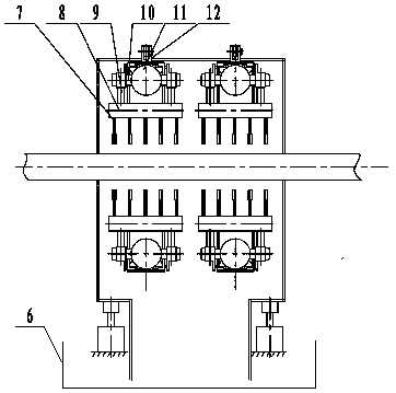
[0033] On the basis of Example 1, such as figure 1 and figure 2 As shown, the water spray ring 1 includes a water supply pipe 11, the water supply pipe 11 is an annular steel pipe, and several branch pipes 10 connected with the annular steel pipe are evenly distributed on both sides along the circumferential direction, and the branch pipe 10 is vertically connected with the swing arm 9. One end of the arm is driven by a power unit 12, and the other end is connected to the nozzle manifold 8, and several nozzles 7 are installed at the end of the nozzle manifold 8.
[0034] It should be noted that since the power device 12 is a prior art, its specific structure is not taken as the protection point of the present invention, and will not be described in detail here.
[0035] The power device 12 in the water spray ring 1 drives the swing arm 9 to rotate a certain angle around the center line of the branch pipe 10, so that the water sprayed from the nozzle 7 is sprayed on the outer...
Embodiment 3
[0038] On the basis of Embodiment 1, the lifting guide device 5 driving its lifting is installed below the frame 4. It should be noted that the lifting guide device 5 is an existing structure. As a preference, the present embodiment selects an oil cylinder or an electric motor Push rod, lifting guiding device 5 drive frame 4 overall lifting, make water spray ring, machine cover and frame integral lift certain distance, guarantee that water spray ring is consistent with steel pipe center height.
[0039] The annular quenching device also includes a machine cover 2 that is covered on the water spray ring 1 to prevent the quenching water from splashing everywhere. The frame 4 and the machine cover 2 cover the water spray ring together to prevent the quenching water from splashing everywhere.
[0040] The lower surface of the frame 4 is perforated and welded with a deflector 14 to divert the quenching water. A water tank 6 is arranged below the deflector 14 to guide the quenching w...
PUM
 Abstract
Description
Claims
Application Information