Film forming apparatus
A film-forming device and film-forming chamber technology, applied in gaseous chemical plating, crystal growth, coating and other directions, can solve the problems of exhausting or time-consuming purification of the film-forming chamber
- Summary
- Abstract
- Description
- Claims
- Application Information
AI Technical Summary
Problems solved by technology
Method used
Image

Examples
no. 1 approach
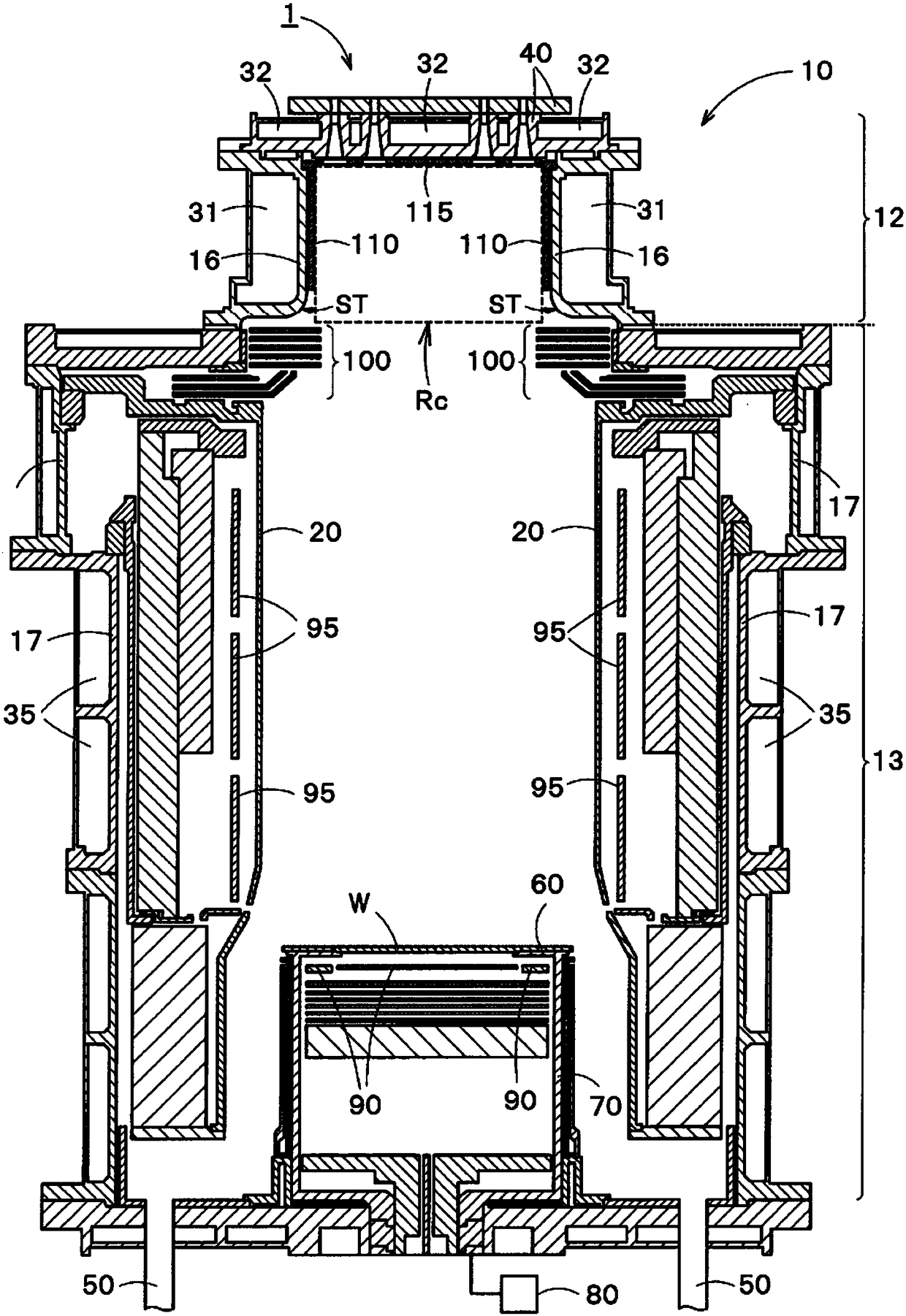
[0024] figure 1 It is a cross-sectional view showing a configuration example of the film formation apparatus 1 of the first embodiment. The film forming apparatus 1 includes a chamber 10, a liner 20, first to third cooling units 31, 32, and 35, a gas supply unit 40, an exhaust unit 50, a heating table 60, a support unit 70, a rotating mechanism 80, and a lower heating unit. 90, upper heater 95 and reflector 100.
[0025] The chamber 10 serving as a film forming chamber can accommodate a substrate W, and is made of stainless steel, for example. The inside of the chamber 10 is decompressed by a vacuum pump (not shown). The chamber 10 has a head 12 and a body 13 . The head portion 12 is provided with a gas supply unit 40 , a first cooling unit 31 , and a second cooling unit 32 . Inside the chamber 10 in the head 12 , the first cooling unit 31 and the second cooling unit 32 suppress the temperature rise of the process gas supplied from the gas supply unit 40 , including source...
no. 2 approach
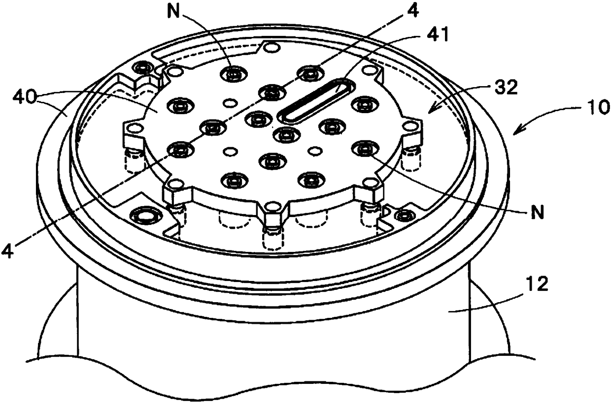
[0057] Figure 5 It is a top view showing an arrangement example of the nozzles N of the gas supply unit 40 of the second embodiment.
[0058] The nozzle Ns is a nozzle for supplying a source gas, and the nozzle Nd is a nozzle for supplying a dopant gas. A dotted circle C12 indicates the position of the inner surface SF12 of the head 12 of the chamber 10 . Most of the nozzles Ns and Nd are arranged inside the dotted circle C12, and are arranged substantially uniformly on the concentric circles C1 to C3 having the center C of the dotted circle C12 as a common center. The center C is the center of the substrate W when viewed from above the surface of the substrate W. As shown in FIG. Among the concentric circles C1 to C3 , the concentric circle C1 is the closest to the center C of the substrate W, the concentric circle C2 is the second closest to the center C, and the concentric circle C3 is the farthest from the center C. In addition, the concentric circles C1 to C3 are virt...
no. 3 approach
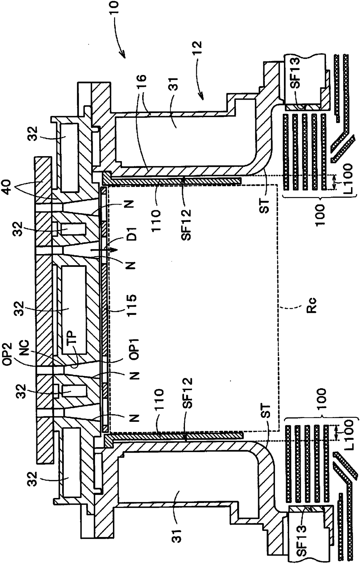
[0063] Figure 7 It is a sectional view showing an example of the shape of the nozzle N of the third embodiment. figure 1 as well as figure 2 The nozzle N shown has a cone TP. However, if Figure 7 As shown, the nozzle N of the third embodiment has no cone.
[0064] Figure 7 The nozzle N shown includes a first nozzle portion N1, a second nozzle portion N2, and a third nozzle portion N3. The first to third nozzle portions N1 to N3 are sequentially provided from the first opening OP1 to the second opening OP2. The side surfaces of the first to third nozzle portions N1 to N3 are all provided substantially parallel to the supply direction D1 of the gas. In addition, the planar shapes of the first to third nozzle portions N1 to N3 may all be substantially circular.
[0065] The first nozzle portion N1 communicates with the temperature rise suppression region Rc of the chamber 10, and has a larger diameter than the diameters of the second and third nozzle portions N2, N3. Th...
PUM
 Abstract
Description
Claims
Application Information