Gap measuring device for thermal state tyre of cement rotary kiln, and application method for gap measuring device

A cement rotary kiln and measuring device technology, which is applied in the direction of mechanical clearance measurement, instruments, measuring devices, etc., can solve the problems of large access, impractical measurement, sliding, etc., and achieve the effect of convenient use, good effect and simple structure

Inactive Publication Date: 2018-05-25
ANHUI WUHU CONCH CONSTR & INSTALLATION ENG
View PDF6 Cites 2 Cited by
  • Summary
  • Abstract
  • Description
  • Claims
  • Application Information

AI Technical Summary

Problems solved by technology

[0002] At present, due to the different temperatures of the gear wheels and the kiln shell during the operation of the cement rotary kiln, the gaps between the cold state and the hot state are very different, but what is actually needed is the largest upper gap in the hot state during operation, and the cement The gap between the rotary kiln and the kiln can’t be measured in practice; now, the

Method used


Image

  • Gap measuring device for thermal state tyre of cement rotary kiln, and application method for gap measuring device
  • Gap measuring device for thermal state tyre of cement rotary kiln, and application method for gap measuring device
  • Gap measuring device for thermal state tyre of cement rotary kiln, and application method for gap measuring device

Examples


Embodiment 1

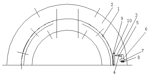
[0020] Such as figure 1 , 2 As shown, a cement rotary kiln hot tire gap tester, including: cement rotary kiln shell 1, kiln wheel 2, is characterized in that: it is also provided between the cement rotary kiln shell 1, kiln wheel 2 Set between: the marking body of the marked travel track set in the gap with the cement rotary kiln shell;

[0021] A telescoping sleeve structure that can be connected with the marking body to control the stretching of the marking body; the marking body is a pencil 3 arranged in the telescopic sleeve structure.

[0022] Connect the connection structure between the cement rotary kiln cylinder body 1 and the telescopic sleeve structure; the telescopic sleeve structure includes a pen cover body 4 and a telescopic spring 5 arranged in the pen cover body 4 and a connecting seat 6 arranged at the bottom of the pen cover body 4, The position of the connection structure is the first connection magnet 7 arranged at the bottom of the connection seat 6 and ...

Embodiment 2

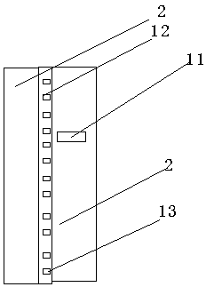
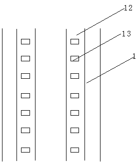
[0026] Such as image 3 , 4 As shown, another cement rotary kiln thermal tire gap tester includes: cement rotary kiln cylinder 1, kiln tire belt 2, and is characterized in that: a cement rotary kiln cylinder 1, kiln tire belt 2 is set between Infrared emitter 11, and a group of infrared collection line belts 12 arranged in gaps are arranged on cement rotary kiln shell 1, gaps are arranged between two infrared collection line belts 12, and two infrared collection line belts are evenly distributed longitudinally The dot matrix identification block 13 of the infrared emitter 11 and the array identification block 13 on the 2 infrared collection line belts 12 after the cement rotary kiln shell 1 and the kiln wheel belt 2 are operated, and at the same time, When there is a gap between the kiln shell and the inner circle of the wheel belt, the contact array recognition block 13 of the infrared emitter 11 stroke presents a curved motion trajectory, which is approximately a semicircul...


PUM


Abstract

The invention provides a gap measuring device for a thermal state tyre of a cement rotary kiln, and the gap measuring device comprises a cement rotary kiln barrel and a kiln tyre. The gap measuring device is characterized in that a marking body which is disposed at an interval with the cement rotary kiln barrel and can mark a travel track, a telescoping sleeve structure which is connected with themarking body and can control the stretching and withdrawing of the marking body, a connecting structure which is connected between the cement rotary kiln barrel and the telescoping sleeve structure and a track mark presenting device which is connected to the kiln tyre are disposed between the cement rotary kiln barrel and the kiln tyre. The beneficial effects of the invention are that the gap measuring device is simple in structure, is convenient to use, is good in effect; the measuring method can be used for the measuring of loosened gaps of any cement rotary kiln tyre.

Description

technical field [0001] The invention relates to a tire gap in hot state of a cement rotary kiln, in particular to a measuring device for a tire gap in a hot state of a cement rotary kiln and a use method thereof. Background technique [0002] At present, due to the different temperatures of the gear wheels and the kiln shell during the operation of the cement rotary kiln, the gaps between the cold state and the hot state are very different, but what is actually needed is the largest upper gap in the hot state during operation, and the cement The gap between the rotary kiln and the kiln can’t be measured in practice; now, the difference between the tire and the kiln shell is generally divided by the π value to obtain the gap between the wheel and the kiln shell. From the point of view of the situation, the discrepancy is relatively large. It is believed that only the ideal situation of pure rolling of the kiln shell on the inner surface of the tire is considered, but in fact ...

Claims


Application Information

Patent Timeline
IPC IPC(8): G01B5/14G01B11/14
CPCG01B5/14G01B11/14
Inventor 师美高孙杰
Owner ANHUI WUHU CONCH CONSTR & INSTALLATION ENG
Why Eureka
Try Eureka