Trigger automatic layout method and device

An automatic layout and flip-flop technology, which is applied in the fields of instrumentation, computing, electrical digital data processing, etc., can solve problems such as affecting the performance of the local clock system and increasing the clock power consumption of the local clock system.

Active Publication Date: 2021-08-17
LOONGSON TECH CORP
View PDF4 Cites 0 Cited by
  • Summary
  • Abstract
  • Description
  • Claims
  • Application Information

AI Technical Summary

Problems solved by technology

[0005] The present invention provides a flip-flop automatic layout method and device, which are used to solve the phenomenon of overlap of flip-flop classes that still exists after multiple clustering of each flip-flop class in the prior art, which in turn affects the performance of the local clock system , the problem of increasing the clock power consumption of the local clock system

Method used


Image

  • Trigger automatic layout method and device
  • Trigger automatic layout method and device
  • Trigger automatic layout method and device

Examples


specific Embodiment approach

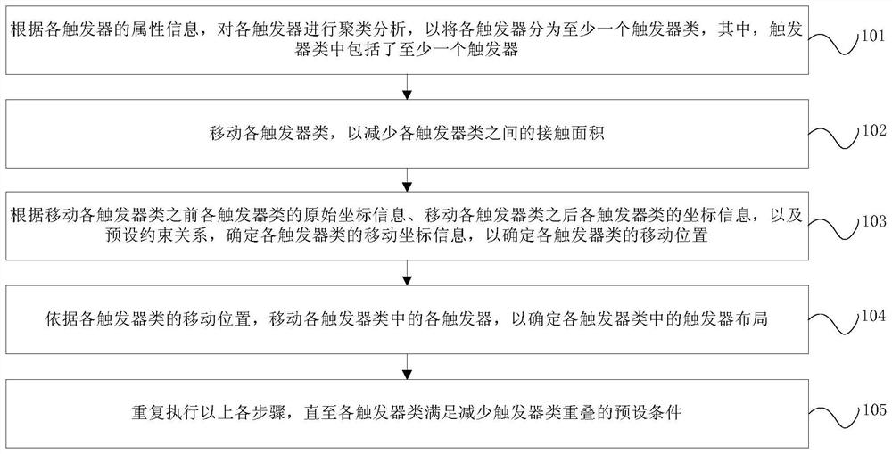
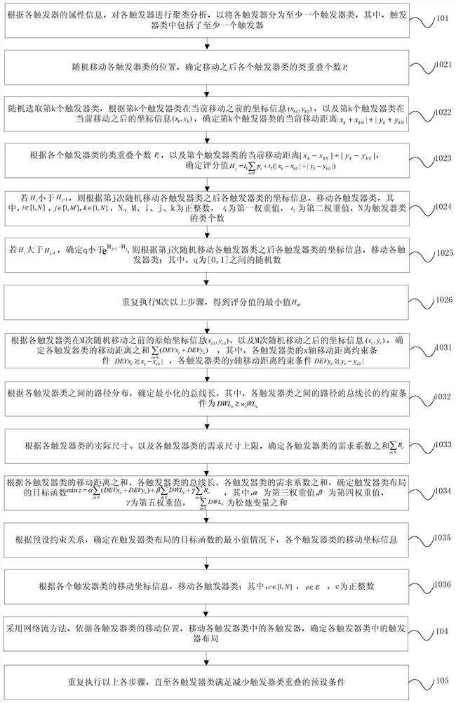
[0077] Alternatively, another specific implementation manner of step 1035 includes:

[0078] According to the actual size of each trigger class, determine the first preset constraint relationship |x between each trigger class a -y b |+|y a -y b |≥(h a + h b ) / 2+(w a +w b ) / 2, and the third preset constraint relationship h between each trigger class c ≥h′ c N c ,w c ≥w′ c N c , where N cis the number of triggers in the cth trigger class;

[0079] Under the constraints of the first preset constraint relationship and the third preset constraint relationship, determine the movement coordinate information (x a ,y a ).

[0080] In this embodiment, specifically, first determine a preset constraint relationship, in the preset constraint relationship, and the x-axis movement distance constraint condition of each trigger type, the y-axis movement distance constraint condition of each trigger type, each trigger Under the constraints of the number of paths between trigger...


PUM


Abstract

The present invention provides a method and device for automatic layout of triggers, wherein the method includes: performing cluster analysis on each trigger according to attribute information of each trigger, and dividing each trigger into at least one trigger class; The class includes at least one trigger; move each trigger class to reduce the contact area between each trigger class; according to the original coordinate information of each trigger class before moving each trigger class, and each trigger class after moving each trigger class The coordinate information of each trigger class, and the preset constraint relationship, determine the movement coordinate information of each trigger class to determine the moving position of each trigger class; move each trigger in each trigger class to determine the trigger in each trigger class The above steps are repeated until each trigger class satisfies the preset condition for reducing the overlap of trigger classes. The overlapping phenomenon of flip-flop classes can be reduced, the performance of the local clock system is enhanced, and the clock power consumption of the local clock system is reduced.

Description

technical field [0001] The invention relates to semiconductor integrated circuit technology, in particular to a flip-flop automatic layout method and device. Background technique [0002] In the field of integrated circuit design, the clock system is an important part of the integrated circuit, and in the design of high-performance integrated circuits, the clock system is divided into a global clock system, a regional clock system and a local clock system. The local clock system is connected with the sequential unit flip-flops of the integrated circuit to form a sub-clock tree; the distribution of flip-flops directly affects the performance of the local clock system. In the local clock system, the distribution of flip-flops is required to have a certain regularity or spatial consistency. The regular design of flip-flops is conducive to optimizing the bus length of the local clock system, reducing the clock power consumption of the local clock system, and meeting the requirem...

Claims


Application Information

Patent Timeline
Patent Type & Authority Patents(China)
IPC IPC(8): G06F30/392
CPCG06F30/392
Inventor 王昊杨梁
Owner LOONGSON TECH CORP
Why Eureka
Try Eureka