
Electromagnetic system for three-phase alternating-current contactor having T-shaped armature structure

A three-phase AC and electromagnetic system technology, applied in the direction of electromagnetic relays, electromagnetic relay details, circuits, etc., can solve problems affecting the reliability of contactor action, aggravate contact arc ablation, and unfavorable contactor life, etc., to reduce The effects of contact bounce, improved electrical life, and simple structure

Pending Publication Date: 2018-05-25
嘉润电气科技有限公司
View PDF0 Cites 0 Cited by
  • Summary
  • Abstract
  • Description
  • Claims
  • Application Information

AI Technical Summary

Problems solved by technology

The electromagnetic three-phase AC contactor has a simple structure, is easy to assemble, and has a wide range of applications. However, the traditional electromagnetic three-phase AC contactor has a high pull-in voltage, and there is a phenomenon of contact bounce during the pull-in process, which not only affects the contactor. Long-term operation reliability, and will aggravate contact arc ablation, which is not conducive to the improvement of contactor life

Method used


Image

  • Electromagnetic system for three-phase alternating-current contactor having T-shaped armature structure
  • Electromagnetic system for three-phase alternating-current contactor having T-shaped armature structure
  • Electromagnetic system for three-phase alternating-current contactor having T-shaped armature structure

Examples


Embodiment 1

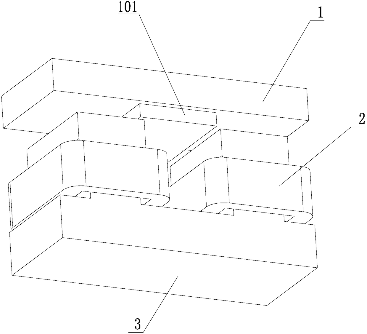
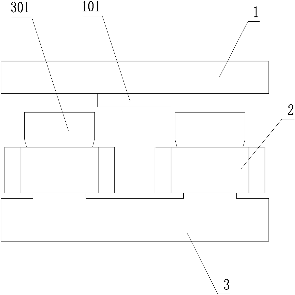
[0038] In the first embodiment, the armature is rotatably located directly above the core, and the axis of rotation of the armature is parallel to the line connecting the two bosses. When the armature and the boss are close to the minimum distance (sucked), the lower bottom surface of the armature is parallel to the boss The upper end surface of the table, and there is a gap between the two, the gap is less than 0.5mm; when released, as the distance between the two increases, the angle between the lower bottom surface of the armature and the upper end surface of the boss gradually increases; In this embodiment, the angle of rotation when the armature is released is 6.9 degrees.

Embodiment 2

[0039] In the second embodiment, the armature is slidingly fitted directly above the iron core, that is, it is installed in a straight line, and the moving direction of the iron core is perpendicular to the upper end surface of the boss; and when the armature is attracted to the boss, that is, when the distance between the two is the smallest, the armature There is a gap between the lower bottom surface of the armature and the upper end surface of the boss, and the gap is less than or equal to 0.5mm; when released, as the distance between the two increases, the lower bottom surface of the armature and the upper end surface of the boss are always parallel.

[0040] In order to avoid collision between the coil and the lower end of the armature, the minimum distance between the upper end of the coil and the bump is greater than 0mm, and there is generally a gap of 1mm-5mm. When the armature is pulled in, the distance between the two is the smallest. The minimum distance is greater tha...


PUM


Abstract

The invention provides an electromagnetic system for a three-phase alternating-current contactor having a T-shaped armature structure. The electromagnetic system comprises an iron core, coils and an armature; two lug bosses are symmetrically arranged on the iron core, so that a U-shaped structure is formed; the two coils separately sleeve the two lug bosses; the armature is just above the iron core, and can be contacted or separated from the end faces of the lug bosses; a protrusion block is arranged on the lower bottom surface of the armature; the protrusion block is positioned between the two lug bosses; an elastic part is arranged on the armature; and, due to the elastic part, the armature has the tendency of moving towards the iron core direction. The electromagnetic system for the three-phase alternating-current contactor having the T-shaped armature structure provided by the invention is simple in structure and convenient to process; the pull-in ampere number of turns of the three-phase alternating-current contactor is reduced; the contact bounce is reduced; the pull-in ampere number of turns is reduced; the suction close to a pull-in position is reduced; therefore, collisionbetween the armature and the iron core is lightened; the contact bounce due to the armature bounce is reduced; and the electrical life of the contactor is prolonged.

Description

Technical field [0001] The invention relates to a three-phase AC contactor, in particular to a T-shaped armature structure three-phase AC contactor electromagnetic system. Background technique [0002] Three-phase AC contactors have a wide range of applications in aerospace, national defense and civil fields. They play the role of control, protection and regulation, and are one of the most basic devices in electrical devices. The electromagnetic three-phase AC contactor has a simple structure, is easy to assemble, and has a wide range of applications. However, the traditional electromagnetic three-phase AC contactor has a high pull-in voltage and there is a contact bounce phenomenon during the pull-in process, which not only affects the contactor The action reliability of long-term work will increase the contact arc ablation, which is not conducive to the improvement of contactor life. Utility model content [0003] [1] Technical problems to be solved [0004] The technical proble...

Claims


Application Information

Patent Timeline
IPC IPC(8): H01H50/18H01H50/36
CPCH01H50/18H01H50/36
Inventor 余铁辉梁慧敏王铁伟
Owner 嘉润电气科技有限公司
Learn More