Antenna module and terminal equipment

A technology for antenna components and terminal equipment, which is applied in the field of communication and can solve problems such as the failure of signal terminal equipment to work normally.

Pending Publication Date: 2018-05-25
GUANGZHOU TUGUIYAO INFORMATION TECH CO LTD
View PDF0 Cites 2 Cited by
  • Summary
  • Abstract
  • Description
  • Claims
  • Application Information

AI Technical Summary

Problems solved by technology

[0004] The purpose of the present invention is to provide an antenna assembly and terminal equipment to solve the technical problem that the existing terminal equipment cannot work norma

Method used


Image

  • Antenna module and terminal equipment
  • Antenna module and terminal equipment
  • Antenna module and terminal equipment

Examples


Embodiment 1

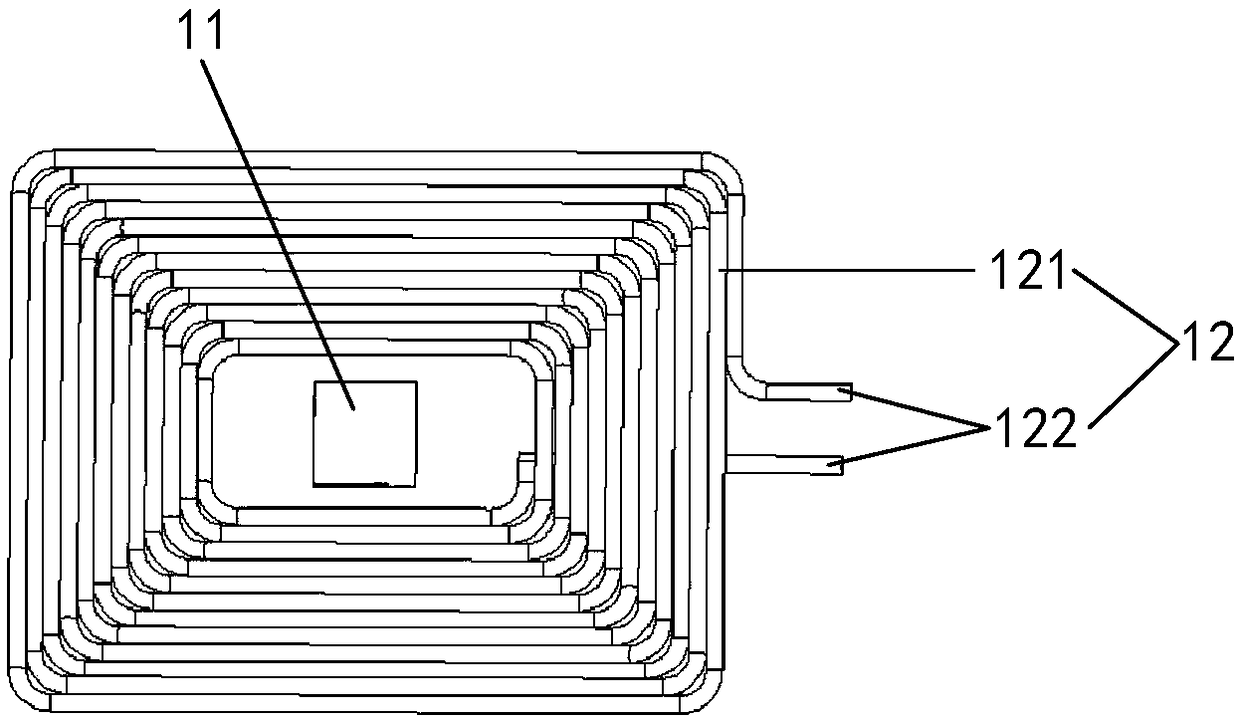
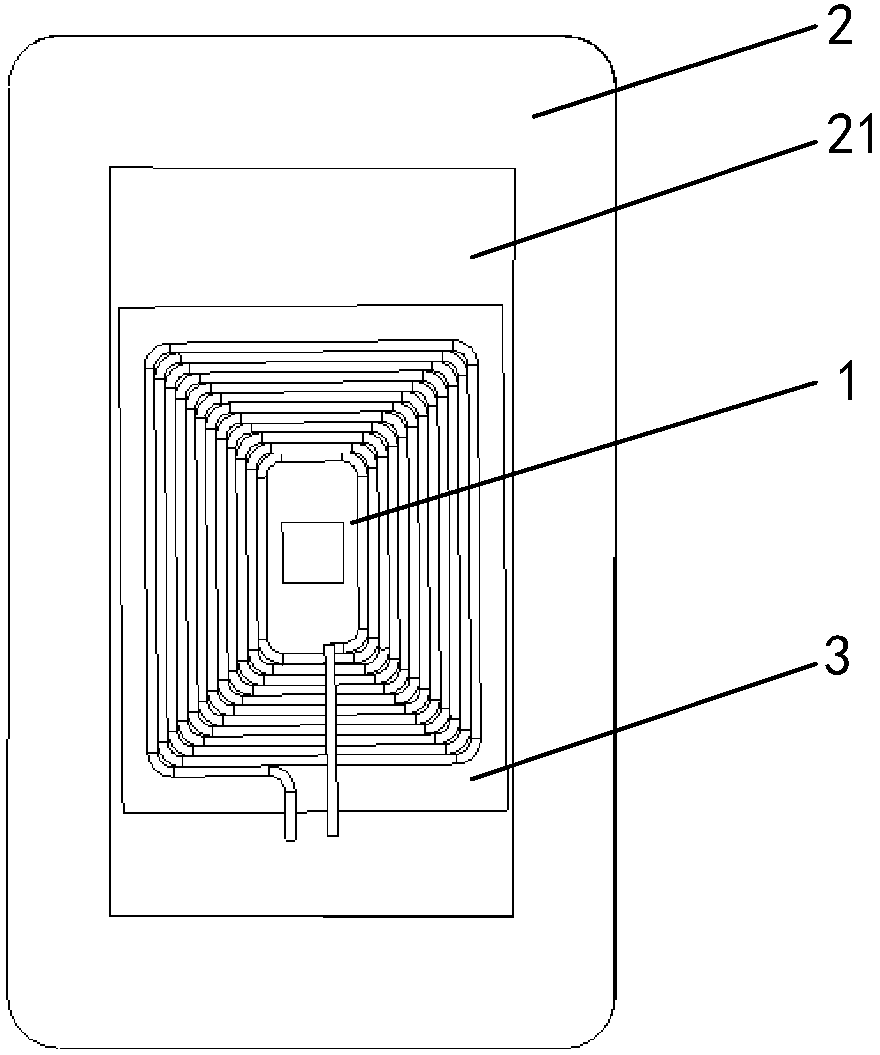
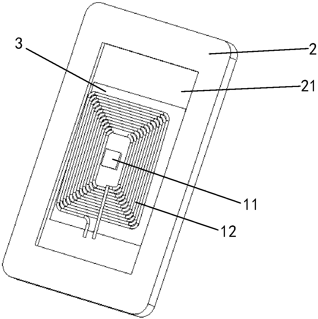
[0025] Such as figure 1 As shown, an antenna assembly 1 according to a preferred embodiment of the present invention includes a first antenna and a second antenna, the first antenna includes a first coil 11, the second antenna includes a second coil 12, and the first The coil 11 is arranged parallel to the second coil 12, and the central axis of the first coil 11 coincides with the central axis of the second coil 12; the first coil 11 and the second coil 12 are symmetrical structure.

[0026] In the embodiment of the present invention, by arranging the first coil 11 and the second coil 12 in a symmetrical structure, the first coil 11 and the second coil 12 are arranged in parallel, and the second coil The central axis of a coil 11 coincides with the central axis of the second coil 12, so as to prevent the second coil 12 from interfering with the first coil 11 and simultaneously prevent the first coil 11 from interfering with the second coil 11. The coil 12 generates interfer...

Embodiment 2

[0040] In this embodiment of the present invention, the difference between the antenna assembly and the terminal device of this embodiment and Embodiment 1 is that the first antenna in this embodiment is a UWB antenna, and the second antenna is a wireless charging antenna. Wherein, the UWB antenna includes a UWB antenna coil, the wireless charging antenna includes a wireless charging coil, the UWB antenna coil is located in the middle of the wireless charging coil, and the UWB antenna coil and the wireless charging coil are on the same horizontal plane superior. By arranging the UWB antenna coil in the middle of the wireless charging coil, and making the UWB antenna coil and the wireless charging coil on the same horizontal plane, the strong magnetic field of the wireless charging coil is prevented from affecting the UWB antenna. The coil generates interference, and at the same time, it can prevent the UWB antenna coil from interfering with the wireless charging coil, so as to...


PUM


Abstract

The invention relates to the technical field of communication, and discloses an antenna module and terminal equipment. The antenna module comprises a first antenna and a second antenna. The first antenna comprises a first coil, the second antenna comprises a second coil, the first coil is parallel to the second coil, and the central axis of the first coil coincides with that of the second coil; the first coil and the second coil are both of a symmetrical structure. The first coil and the second coil are arranged into the symmetrical structures, meanwhile, the first coil is parallel to the second coil, and the central axis of the first coil coincides with that of the second coil to avoid interference by the second coil to the first coil and also avoid interference by the first coil to the second coil, so that it is ensured that the first coil and the second coil can work normally, it is effectively avoided that the terminal equipment cannot work normally due to mutual signal interference between antennas of two different sizes and different frequency bands, and normal use of the terminal equipment is guaranteed.

Description

technical field [0001] The present invention relates to the technical field of communications, in particular to an antenna assembly and a terminal device. Background technique [0002] With the continuous development and progress of the economy and society, wireless communication, as a communication method that uses the characteristics of electromagnetic wave signals to propagate in free space for information exchange, is known for its low cost, high adaptability, high scalability and convenience. It is widely used in people's daily life, and wireless communication has gradually become an indispensable part of the information age. Among them, UWB (Ultra-Wideband, ultra-wideband wireless communication) and NFC (Near Field Communication, short-range wireless communication) are commonly used wireless communication technologies. [0003] The antenna is one of the important components in wireless communication technology. It can convert the guided wave propagating on the transmi...

Claims


Application Information

Patent Timeline
IPC IPC(8): H01Q1/50H01Q1/52H01Q7/00H01Q21/30
CPCH01Q1/50H01Q1/521H01Q1/526H01Q7/00H01Q21/30
Inventor 裴玉奎
Owner GUANGZHOU TUGUIYAO INFORMATION TECH CO LTD
Why Eureka
Try Eureka