Arterial puncture guide device and use method thereof
A guiding device and arterial puncture technology, applied in the directions of puncture needle, application, guiding needle, etc., to achieve the effect of simple structure, avoiding patient discomfort and physical injury, and improving work efficiency
- Summary
- Abstract
- Description
- Claims
- Application Information
AI Technical Summary
Problems solved by technology
Method used
Image
Examples
Embodiment 1
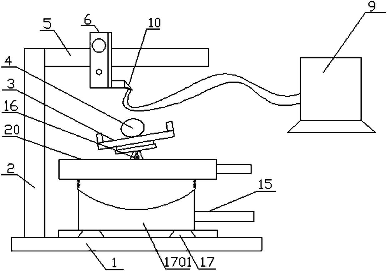
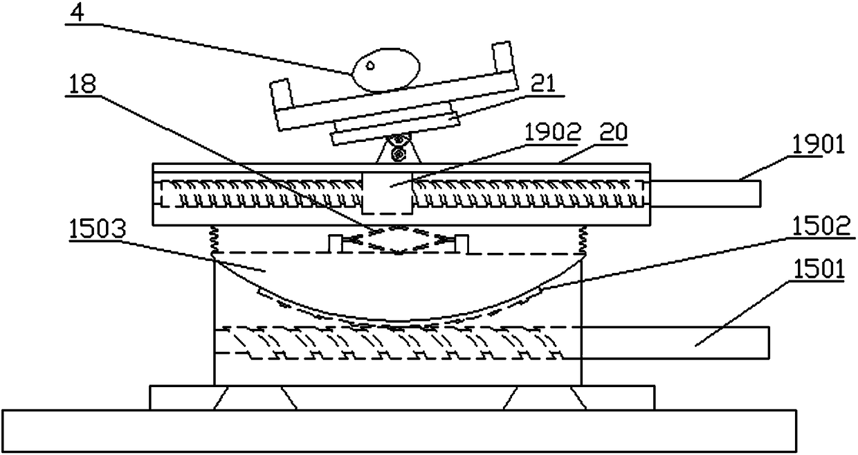
[0049] Example 1, such as figure 1 , figure 2 , Figure 5 and Image 6 As shown, there is one vibration detection piece 7, and the first strain gauge 8 is selected as the sensing mechanism. An anti-jamming frame 10 is arranged around the periphery of the vibration detection piece 7, and the anti-jamming frame 10 is provided as a lateral overhang. The detection contacts of the vibration detection piece 7 701 protrudes downward from the anti-jamming frame 10; the X-Y-Z linear displacement mechanism includes a bottom X-Y-Z displacement system arranged between the bearing table 3 and the chassis 1 and a top X-Z displacement system arranged between the vibration detection piece 7 and the cantilever 5, X-Y-Z The overturning mechanism includes a bottom Y-axis overturning system arranged between the loading platform 3 and the chassis 1, the Y-axis direction is the longitudinal direction of the loading platform 3, the arm 4 is selected as the position to be punctured, and the radial...
Embodiment 2
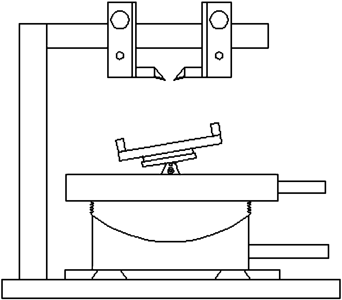
[0064] Embodiment 2, as the optimization of embodiment 1, such as image 3 As shown, the vibration detection pieces 7 are two arranged along the lateral direction of the site to be punctured, and the two vibration detection pieces 7 are symmetrically arranged in the form of two adjacent detection contacts 701, as shown in image 3 As shown in , the distance between the two is greater than the diameter of the puncture needle 22, and the periphery of the two vibration detection pieces 7 is surrounded by an anti-interference frame 10. The head 701 protrudes downwards from the anti-interference frame 10; the X-Y-Z linear displacement mechanism includes a bottom X-Y-Z displacement system arranged between the bearing table 3 and the chassis 1 and a top X-Z displacement system arranged between the vibration detection piece 7 and the cantilever 5, The X-Y-Z turning mechanism includes a bottom Y-axis turning system arranged between the carrying platform 3 and the chassis 1. The Y-axis ...
Embodiment 3
[0074] Example 3, such as Figure 4 As shown, as a further optimization of embodiment 2, the position to be punctured can be selected from the arm 4 wrist, thigh or instep position, the vibration detection sheet 7 is two arranged along the lateral direction of the site to be punctured, and the two vibration detection sheets 7 are Two detection contacts 701 are arranged symmetrically adjacent to each other, the distance between them is greater than the diameter of the puncture needle 22, and the periphery of the two vibration detection pieces 7 is surrounded by an anti-jamming frame 10, and the lower end surface of each anti-jamming frame 10 is respectively attached with a second strain gauge 1001, such as Figure 5 and Image 6 As shown, the information output end of the second strain gauge 1001 is connected to the strain gauge 9, and the strain gauge 9 displays the waveform diagram of the feedback after the deformation of the second strain gauge 1001; The bottom X-Y-Z displ...
PUM
 Abstract
Description
Claims
Application Information
 - R&D
- Intellectual Property
- Life Sciences
- Materials
- Tech Scout
- Unparalleled Data Quality
- Higher Quality Content
- 60% Fewer Hallucinations
Browse by: Latest US Patents, China's latest patents, Technical Efficacy Thesaurus, Application Domain, Technology Topic, Popular Technical Reports.
© 2025 PatSnap. All rights reserved.Legal|Privacy policy|Modern Slavery Act Transparency Statement|Sitemap|About US| Contact US: help@patsnap.com


