
Combined pressurized liquid stop clip

A liquid stop clip and combined technology, applied in the field of medical devices, can solve problems ranging from a few hours to dozens of hours or even longer, increasing the nursing workload, and thrombus blocking the cannula, saving medical expenses and reducing nursing work. , the effect of improving the quality of medical care

Pending Publication Date: 2018-05-29
谢世庚
View PDF15 Cites 0 Cited by
  • Summary
  • Abstract
  • Description
  • Claims
  • Application Information

AI Technical Summary

Problems solved by technology

However, the general indwelling time ranges from several hours to dozens of hours or even longer. After closing, there is residual liquid in the indwelling needle, and the blood will penetrate into the residual liquid in the cannula. After reaching a certain concentration and time, a thrombus will form. plugging sleeve
[0003] For this reason, the routine operation of indwelling needles stipulates that when suspending infusion for indwelling, the tube should be flushed with normal saline, then sealed with anticoagulant, and repeated every 6-8 hours, which will not only increase the workload of nursing but also increase the risk of infection. chance, increased medical costs

Method used


Image

  • Combined pressurized liquid stop clip
  • Combined pressurized liquid stop clip
  • Combined pressurized liquid stop clip

Examples


Embodiment Construction

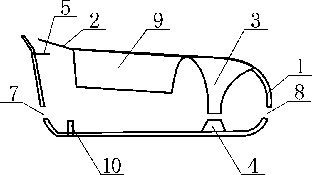
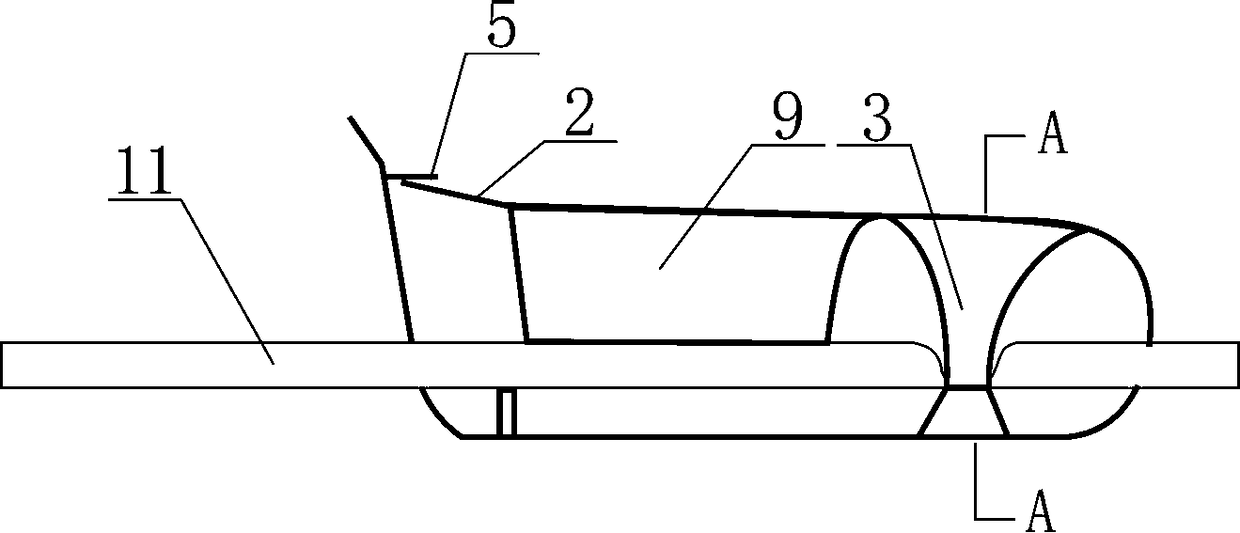
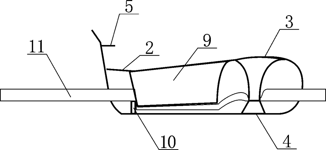
[0017] Such as figure 1 As shown, the combined pressurized liquid-stop clip includes a U-shaped plate 1, a liquid-stop hook 5, an elastic plate 2, a liquid-stop upper clamp bar 3, a liquid-stop lower clamp bar 4, a pressure block 9 and a clamp bar 10. The U-shaped plate 1 is an outwardly expanded arcuate structure, and the left and right through holes 7 and 8 are respectively provided on the left and right side walls of the U-shaped plate, and the liquid medicine conduit 11 passes through the left through hole 7 and the right through hole 8 , one end of the elastic plate 2 is connected to one end of the U-shaped plate 1, and the other end is a free end, the liquid-stop hook 5 is set at the other end of the U-shaped plate 1, and the liquid-stop upper clip 3 and the pressing block 9 are fixed on the elastic plate 2 The bottom surface of the bottom surface, the clip bar 10 and the bottom clip bar 4 of the liquid stop are erected on the U-shaped plate 1, the U-shaped plate 1, the ...


PUM


Abstract

The invention discloses a combined pressurized liquid stop clip comprising a U-shaped plate, a liquid stop hook, an elastic board, a liquid-stop upper clip, a liquid-stop lower clip, a clip, a briquetting block and a clip. The combined pressurized liquid stop clip is characterized in that when a free end of the elastic board is hooked by the liquid stop hook, a lower end of the liquid-stop upper clip is in contact with an upper end of the liquid-stop lower clip; a liquid medicine conduit clamping groove located between the lower end face of the liquid-stop upper clip and the upper end face ofthe liquid-stop lower clip clamps a liquid medicine conduit tightly; then when the elastic board continues to be pressed down, the side of the briquetting block cooperates with the clip to block a flow channel of the liquid medicine conduit; the bottom surface of the briquetting block squashes one section of the liquid medicine conduit; liquid flows through a stop point of the liquid medicine conduit clamped by the liquid-stop upper clip and the liquid-stop lower clip. The pressurized liquid stop clip has the advantages of having a simple structure with the adoption of the above structure, being easy to implement and low in cost with the combined pressurized liquid stop clip as a whole structure and integrally formed by injection molding, realizing the functions of stopping liquid and pressurizing flushing tubes through the pressing of the elastic board, and being anti-thrombotic and anti-clogging.

Description

technical field [0001] The invention relates to a medical device, in particular to a liquid-stopping clip for an intravenous indwelling needle. Background technique [0002] Indwelling needles, central venous catheters, etc. must block the liquid flow channel during indwelling. Commonly used clips, one-handed clips, etc., are called stop clips. In the process of closing the stop clip, many factors can cause negative pressure in the catheter. Even a slight negative pressure will cause blood to flow into the cannula of the indwelling needle, which will quickly form a thrombus and block the cannula. For this reason, in recent years, there have been a variety of patents and products for elastic hemostatic clips or positive pressure hemostatic clips, which have a positive effect on preventing blood backflow and thrombus formation after clamping hemostatic clips. However, the general indwelling time ranges from several hours to dozens of hours or even longer. After closing, there...

Claims


Application Information

Patent Timeline
Patent Type & Authority Applications(China)
IPC IPC(8): A61M5/175
CPCA61M5/16813
Inventor 谢世庚谢逸铭
Owner 谢世庚
Learn More