Press-fitting device for shock absorber working cylinder and compression valve
A working cylinder and compression valve technology, applied in metal processing equipment, metal processing, manufacturing tools, etc., can solve the problems of poor cleanliness of the shock absorber assembly, affecting the performance of the shock absorber, difficult to clean, etc. The effect of poor degree of cleanliness, improved cleanliness, and convenient daily cleaning
- Summary
- Abstract
- Description
- Claims
- Application Information
AI Technical Summary
Problems solved by technology
Method used
Image
Examples
Embodiment 1
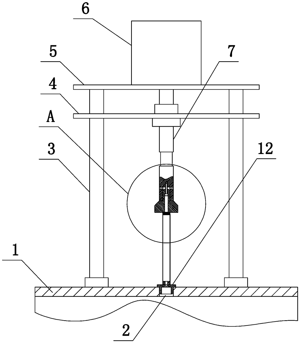
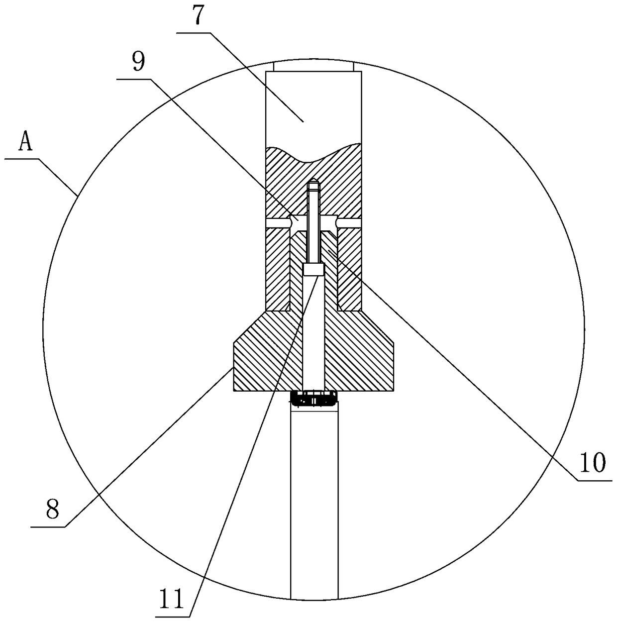
[0032] Such as Figure 1 to Figure 3 As shown, the present invention comprises equipment frame 1, and the upper end surface of equipment frame 1 is provided with press-fit assembly and positioning hole 2, and press-fit assembly comprises guide column 3, guide plate 4, bearing plate 5, and guide column 3 is four (Two are shown in the figure), the guide plate 4 is slidably arranged on the four guide columns 3, the load bearing plate 5 is fixedly connected to the upper ends of the four guide columns 3, and the force bearing plate 5 is provided with a telescopic mechanism 6. In this embodiment The telescopic mechanism 6 is a telescopic cylinder, the upper end of the telescopic mechanism 6 is externally connected to a compressed air supply device (not shown), the lower end of the telescopic mechanism 6 is fixedly connected to the upper end surface of the guide plate 4, and the lower end surface of the guide plate 4 is fixedly connected to the pressure rod 7, The lower end of the pr...
Embodiment 2
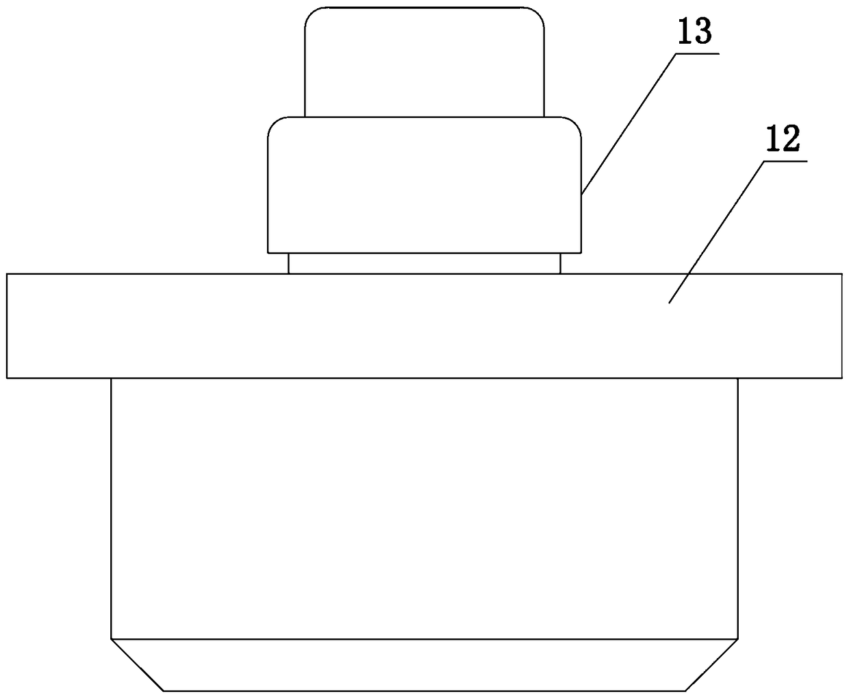
[0034] Such as Figure 1 to Figure 4As shown, the present invention comprises equipment frame 1, and the upper end surface of equipment frame 1 is provided with press-fit assembly and positioning hole 2, and the matching design of press-fit assembly and positioning hole 2 is a plurality of, and press-fit assembly includes guide post 3, guide Plate 4, force bearing plate 5, four guide columns 3, guide plate 4 is slidably arranged on the four guide columns 3, force bearing plate 5 is fixedly connected to the upper ends of the four guide columns 3, and a telescopic mechanism is arranged on the force bearing plate 5 6. In this embodiment, the telescopic mechanism 6 is a telescopic cylinder. The upper end of the telescopic mechanism 6 is externally connected to a compressed air supply device (not shown in the figure), and the lower end of the telescopic mechanism 6 is fixedly connected to the upper end surface of the guide plate 4. The lower end surface of the guide plate 4 The pre...
Embodiment 3
[0037] Such as Figure 1 to Figure 3 , Figure 5 As shown, the present invention comprises equipment frame 1, and the upper end surface of equipment frame 1 is provided with press-fit assembly and positioning hole 2, and press-fit assembly comprises guide column 3, guide plate 4, bearing plate 5, and guide column 3 is four , the guide plate 4 is slidably arranged on the four guide columns 3, the force bearing plate 5 is fixedly connected to the upper ends of the four guide columns 3, the force bearing plate 5 is provided with a telescopic mechanism 6, and the telescopic mechanism 6 is a telescopic cylinder in the present embodiment, and the telescopic The upper end of the mechanism 6 is externally connected with a compressed air supply device (not shown in the figure), the lower end of the telescopic mechanism 6 is fixedly connected with the upper end surface of the guide plate 4, the lower end surface of the guide plate 4 is fixedly connected with the pressure rod 7, and the ...
PUM
 Abstract
Description
Claims
Application Information
 - R&D
- Intellectual Property
- Life Sciences
- Materials
- Tech Scout
- Unparalleled Data Quality
- Higher Quality Content
- 60% Fewer Hallucinations
Browse by: Latest US Patents, China's latest patents, Technical Efficacy Thesaurus, Application Domain, Technology Topic, Popular Technical Reports.
© 2025 PatSnap. All rights reserved.Legal|Privacy policy|Modern Slavery Act Transparency Statement|Sitemap|About US| Contact US: help@patsnap.com


