Aircraft fly-by-wire braking system with automatic braking function

A technology of automatic braking and braking system, which is applied in the direction of aircraft braking arrangement, automatic starting device, braking transmission device, etc. The effect of runway utilization and equipment utilization, high reliability, flexible and convenient use

Active Publication Date: 2020-06-16
XIAN AVIATION BRAKE TECH
View PDF22 Cites 0 Cited by
  • Summary
  • Abstract
  • Description
  • Claims
  • Application Information

AI Technical Summary

Problems solved by technology

[0005] In order to overcome the problems of complex configuration, frequent faults, difficulty in troubleshooting and positioning, low reliability in use, multiple logical relationships and even potential safety hazards in the existing braking system, the present invention proposes an aircraft electric brake system with automatic braking function. transmission brake system

Method used


Image

  • Aircraft fly-by-wire braking system with automatic braking function
  • Aircraft fly-by-wire braking system with automatic braking function

Examples


Embodiment 1

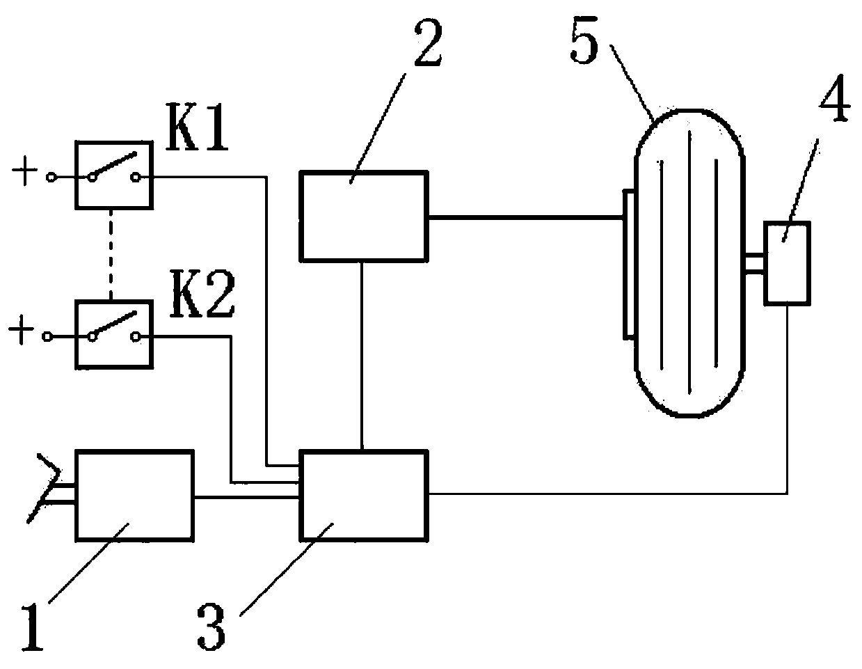
[0029] This embodiment is an aircraft fly-by-wire hydraulic braking system with a first-level automatic braking capability, including a braking command sensor 1 , a control box 3 , an electro-hydraulic servo valve 2 , an automatic braking switch K and a speed sensor 4 . Among them: the first automatic brake switch K1 and the second automatic brake switch K2 are installed in the cockpit; the first automatic brake switch K1 and the second automatic brake switch K2 are electrically connected to the electro-hydraulic servo valve 2 through cables; the first automatic brake switch The switch K1 and the second automatic brake switch K2 are manually operated by the driver to control and provide an enabling electric signal to the electro-hydraulic servo valve 2 to turn on or off the automatic brake. According to the received signal, the brake port of the electro-hydraulic servo valve 2 outputs hydraulic pressure. If the hydraulic pressure is used for automatic braking, or there is no hy...

Embodiment 2

[0045] This embodiment is an aircraft fly-by-wire hydraulic braking system with automatic braking capability. The difference from the technical solution of Embodiment 1 is that the aircraft fly-by-wire hydraulic braking system of this embodiment is a two-stage automatic braking system.

[0046] see figure 2 . This embodiment includes: a brake command sensor 1 , a control box 3 , an electro-hydraulic servo valve 2 , a first automatic brake switch K1 , a second automatic brake switch K2 and a speed sensor 4 . Among them: the first automatic brake switch K1 and the second automatic brake switch K2 are installed in the cockpit; the first automatic brake switch K1 and the second automatic brake switch K2 are electrically connected to the control box 3 through cables; the first automatic brake switch K1 1. The second automatic brake switch K2 is manually operated by the driver, and the control box 3 is provided with an enabling electric signal to turn on or off the automatic brake...


PUM


Abstract

The invention provides an airplane electric transmission braking system with an automatic braking function. A conventional braking system is composed of a braking command sensor, a control box, an electric-hydraulic servo valve and a speed sensor; a conventional anti-skidding control system is composed of the control box, the electric-hydraulic servo valve and the speed sensor; and an automatic braking system is composed of an automatic braking switch K or a first automatic braking switch K1, a second automatic braking switch K2, the speed sensor and the control box. All the automatic brakingswitches supply automatic braking switch-on or switch-off enabled electric signals to the control box, the control box controls that an automatic braking current signal is sent or not sent to the electric-hydraulic servo valve, and therefore automatic braking control is achieved. The operation and selection range of the normal braking system is completed and expanded, the potential of the brakingsystem can be brought into full play, the landing sliding distance is shortened by about 35%, airplane take-off and landing safety is guaranteed, the airport runway use rate and the equipment use rateare increased, and economic, social and military benefits are remarkable.

Description

technical field [0001] The invention relates to an aircraft wheel fly-by-wire braking system, in particular to an aircraft fly-by-wire braking system with automatic braking capability. Background technique [0002] The aircraft wheel brake system is a component of modern aircraft landing gear, and is the basic guarantee equipment for the safe operation of aircraft take-off, landing roll and ground taxi control. Prevent punctured tires. Experimental research and use have shown that under certain conditions, the use of automatic braking can effectively shorten the landing roll distance of the aircraft. Automatic braking has also been long-awaited to relieve the driver of the load during safety-critical landings. At present, general aircraft do not have the ability to automatically brake, including aircraft using fly-by-wire brakes. When braking, the driver needs to step on the brake pedal or control the brake handle to manipulate the brake valve or brake command sensor. Only...

Claims


Application Information

Patent Timeline
Patent Type & Authority Patents(China)
IPC IPC(8): B60T7/12B60T13/66B60T13/68B64C25/44
CPCB60T7/12B60T13/662B60T13/686B64C25/44
Inventor 何永乐何文静王红玲
Owner XIAN AVIATION BRAKE TECH
Why Eureka
Try Eureka