Check patentability & draft patents in minutes with Patsnap Eureka AI!

Steel wire rope guide device and rotary drilling rig

A technology of a guiding device and a rotary drilling rig, which is applied in the directions of rotary drilling rigs, hoisting devices, rotary drilling, etc., can solve the problem of serious friction between the wire rope and the side wall of the pulley groove, and achieve the effect of improving the service life.

Pending Publication Date: 2018-05-29
SANY HEAVY IND CO LTD (CN)
View PDF0 Cites 1 Cited by
  • Summary
  • Abstract
  • Description
  • Claims
  • Application Information

AI Technical Summary

Problems solved by technology

However, as the drum rotates, the tangent point between the wire rope and the drum moves along the axis of the drum; since the drum has a certain length, the distance between the wire rope and the center plane of the pulley (the center plane of symmetry perpendicular to the axis of the pulley) The included angle also changes accordingly. When the included angle is larger, the friction between the wire rope and the side wall of the pulley groove is more serious.

Method used


Image

  • Steel wire rope guide device and rotary drilling rig
  • Steel wire rope guide device and rotary drilling rig
  • Steel wire rope guide device and rotary drilling rig

Examples


Embodiment

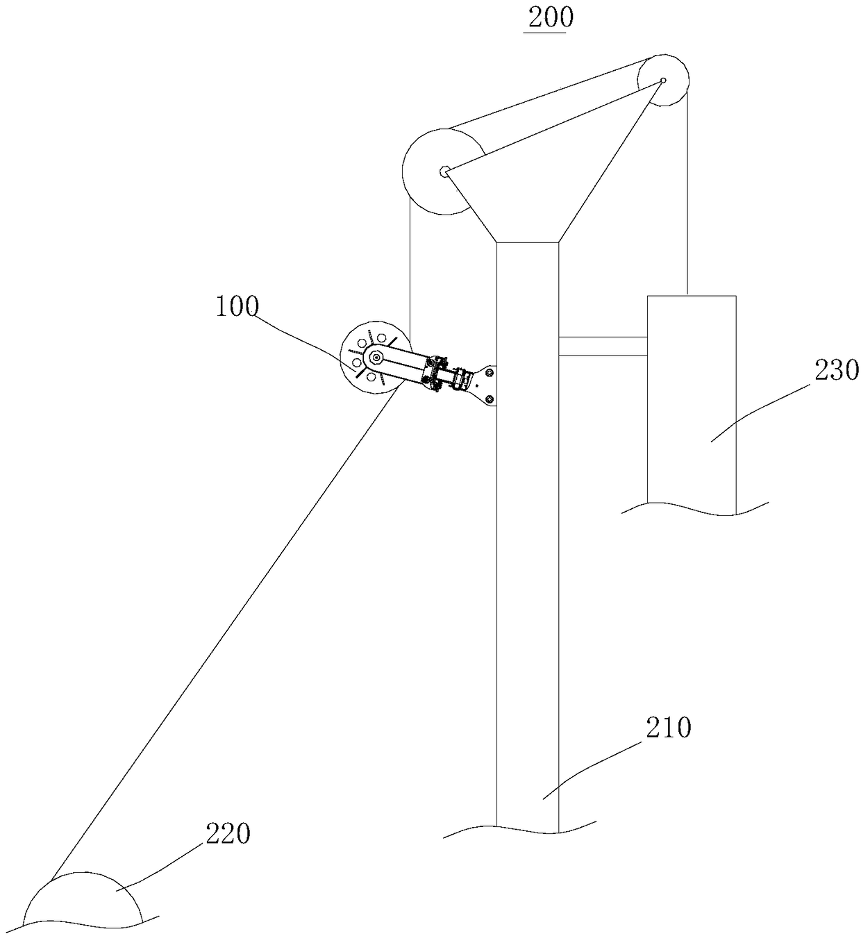
[0046] Such as figure 1 , figure 1 It is a partial structural schematic diagram of the rotary drilling rig 200 . This embodiment provides a rotary drilling rig 200, which mainly includes a chassis (not shown in the figure), a winch 220, a mast 210 and a drill rod, the winch 220 and the mast 210 are respectively connected to the chassis, and the mast 210 is A wire rope guiding device 100 is provided, one end of the wire rope is wound on the winch 220, and the other end is connected to the upper end of the drill pipe after winding around the wire rope guiding device 100.

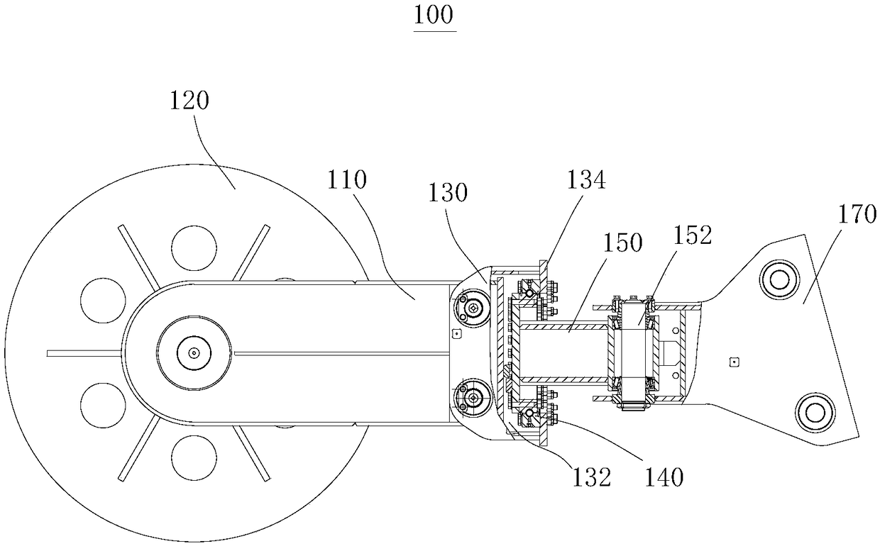
[0047] Such as figure 2 , figure 2is a structural schematic diagram of the wire rope guiding device 100 , which mainly includes a connecting frame 110 , a slewing support 140 , a swing arm 150 and a support 170 . One end of the connecting frame 110 is provided with a pulley 120, and the other end is rotatably connected with the swing arm 150 through the slewing support 140; .

[0048] Specifically, the...


PUM


Abstract

The invention provides a steel wire rope guide device and a rotary drilling rig, and belongs to the field of engineering machines. The steel wire rope guide device mainly comprises a connecting frame,a rotary support, a swing arm and a support; one end of the connecting frame is provided with a pulley, the other end of the connecting frame is rotatably connected with the swing arm through a connecting base, the free end of the swing arm is connected with the support through a pin shaft, and the support is connected with a mast, the rotary support is arranged in the containing space of the connecting base, the swing arm is connected with the connecting base through the rotary support, and due to the fact that the rotary support is arranged in the containing space of the connecting base, the rotary support does not need to be additionally provided with a protection cover. The connecting base achieves the connecting effect, the protection effect is achieved, the whole structure is more compact. Through the rotary drilling rig of the structure, the steel wire rope guide device is adopted, and the service life of the steel wire rope and the pulley can be prolonged.

Description

technical field [0001] The invention relates to the field of engineering machinery, in particular to a steel wire rope guiding device and a rotary drilling rig. Background technique [0002] Rotary drilling rig is a comprehensive drilling rig, which can use a variety of bottom layers, and has the characteristics of fast hole forming speed, less pollution, and strong mobility. There are two ways to install the main winch of the rotary drilling rig in the prior art: one is to install the main winch on the mast and use a winding drum; the other is to install the main winch on the chassis Above, it belongs to the rear of the main winch, and adopts a single-layer winding drum. [0003] The rear position of the main winch will cause the mast to bear a large backward bending moment. In order to solve this problem, it is generally necessary to set a guide pulley on the mast so that the wire rope is wound on the drum after passing around the guide pulley, thereby reducing the The b...

Claims


Application Information

Patent Timeline
IPC IPC(8): B66D1/36E21B19/02E21B3/00
CPCE21B3/00E21B19/02B66D1/36B66D2700/026
Inventor 于帅安聪锋张世平
Owner SANY HEAVY IND CO LTD (CN)
Features
  • R&D
  • Intellectual Property
  • Life Sciences
  • Materials
  • Tech Scout
  • Unparalleled Data Quality
  • Higher Quality Content
  • 60% Fewer Hallucinations
Learn More