
Wind collection power generating device

A power generation device and wind collection technology, which is applied in wind power generation, photovoltaic power generation, wind power generators, etc., can solve problems such as greater influence of light energy, inability to transplant wind power generation, and breakthroughs that have not reached the practical level. Simple and efficient wind energy conversion

Inactive Publication Date: 2018-05-29
WEIFANG PASADI ECONOMIC & TRADE CO LTD
View PDF0 Cites 0 Cited by
  • Summary
  • Abstract
  • Description
  • Claims
  • Application Information

AI Technical Summary

Problems solved by technology

[0003] The role of electricity in people's production and life is becoming more and more important. Modern electric vehicles are becoming more and more popular. In order to extend the battery life of electric vehicles, automobile manufacturers have made a lot of clever tricks, such as increasing the battery capacity, adding solar panels on the top, or It is to install charging piles along the road, etc., and these designs have various restrictions on free travel, and none of them have reached a practical breakthrough
Nature's energy collection is nothing more than light energy, wind energy, water energy, etc. The use of light energy is greatly affected by the weather, while traditional wind power generation cannot be transplanted to electric vehicles due to the limitation of the size of the impeller.

Method used


Image

  • Wind collection power generating device
  • Wind collection power generating device
  • Wind collection power generating device

Examples


Embodiment Construction

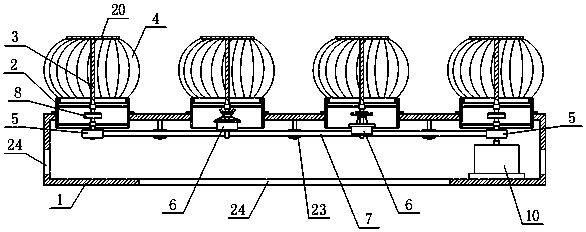
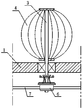
[0034] Referring to the accompanying drawings, the wind collecting power generation device of the present invention includes a box body 1, a plurality of main shafts 3 are rotatably installed on the top wall of the box body 1, the upper part of the main shaft 3 protrudes out of the box body 1 and the overhanging section of the main shaft 3 is connected to a plurality of helical blades 4. The helical blades 4 are spaced around the main shaft 3 and form a spherical body of revolution; the lower part of the main shaft 3 extends into the box 1 and the bottom of the main shaft 3 is equipped with a pulley, which includes two fixed belts at both ends Pulley 5 and a plurality of driving pulleys 6 in the middle, and a timing belt 7 is connected between the two fixed pulleys 5; the bottom ends of the two main shafts 3 at both ends are connected with a pulley shaft 9 through an overrunning clutch mechanism 8, and the two A fixed pulley 5 is fixed on the bottom end of the pulley shaft 9, a...


PUM


Abstract

The invention relates to a wind collection power generating device. The wind collection power generating device comprises a box body; main shafts are rotationally mounted on the top wall of the box body and spherical rotation bodies are mounted at the upper portions of the main shafts; the lower portions of the main shafts extend into the box body and belt wheels are mounted at the bottoms of themain shafts; the belt wheels comprises two fixed belt wheels which are located at the two ends and a plurality of movable belt wheels which are located in the middle; a synchronizing belt is connectedbetween the two fixed belt wheels; the bottom end parts of the two main shafts which are located at the two ends are connected with belt wheel shafts by overrunning clutch mechanisms; the two fixed belt wheels are fixedly mounted at the bottom end parts of the belt wheel shafts and the belt wheel shafts are rotationally mounted on bases; the movable belt wheels are correspondingly vertically mounted at the bottom end parts of the main shafts which are located in the middle in a sliding manner; flail block pressing plate mechanisms which are capable of driving the movable belt wheels to slidedownward and extend into the synchronizing belt are mounted on the main shafts which are located in the middle; an electric generator is mounted in the box body and an input shaft of the electric generator is connected with the bottom end of one belt wheel shaft. The device has the advantages of being simple in structure, convenient to use, high in wind energy transfer efficiency and good in windpower generation effect.

Description

technical field [0001] The invention relates to the field of wind power generation, in particular to a wind collecting and generating device. Background technique [0002] Wind power generation is the main way people use wind energy at present. It uses wind impellers to drive the generator rotor to rotate, thereby converting wind energy into electrical energy. However, most of the current wind power generating devices are large-scale wind power generators, which have huge systems, complex structures, and low utilization rates of wind energy. It is difficult to see wind power generation devices in daily life. [0003] The role of electricity in people's production and life is becoming more and more important. Modern electric vehicles are becoming more and more popular. In order to extend the battery life of electric vehicles, automobile manufacturers have made a lot of clever tricks, such as increasing the battery capacity, adding solar panels on the top, or It is to instal...

Claims


Application Information

Patent Timeline
Patent Type & Authority Applications(China)
IPC IPC(8): F03D9/25F03D15/00F03D3/06F03D9/32F03D13/20F16D41/066F16D43/14H02S10/12
CPCF03D3/062F03D9/007F16D41/066F16D43/14F16D2043/145F03D9/25F03D9/32F03D13/20F03D15/00H02S10/12Y02E10/50Y02E10/728Y02E10/74
Inventor 李翰林郭士增
Owner WEIFANG PASADI ECONOMIC & TRADE CO LTD
Learn More