Optical module structure of pattern projection lamp

A module and pattern technology, applied in optics, optical components, instruments, etc., can solve the problems of affecting the contrast of projected patterns and turning into a piece of background light, so as to achieve simple and easy alignment and positioning, simplify the alignment process, simplify alignment effect

Active Publication Date: 2018-05-29
DONG GUAN LONGIDEAL IND CO LTD
View PDF4 Cites 9 Cited by
  • Summary
  • Abstract
  • Description
  • Claims
  • Application Information

AI Technical Summary

Problems solved by technology

The light rays emitted by the same point on the light source, except the useful light rays incident on the numerical aperture of the fly-eye lens 92 for channel projection, other light rays whose divergence angle is larger than the numerical aperture of the fly-eye lens will be incident on the adjacent The small lens unit forms crosstalk and produces multiple layers of ghosting. Finally, the projected stray light will become a piece of background light, which seriously affects the contrast of the projected pattern.

Method used


Image

  • Optical module structure of pattern projection lamp
  • Optical module structure of pattern projection lamp
  • Optical module structure of pattern projection lamp

Examples


Embodiment 1

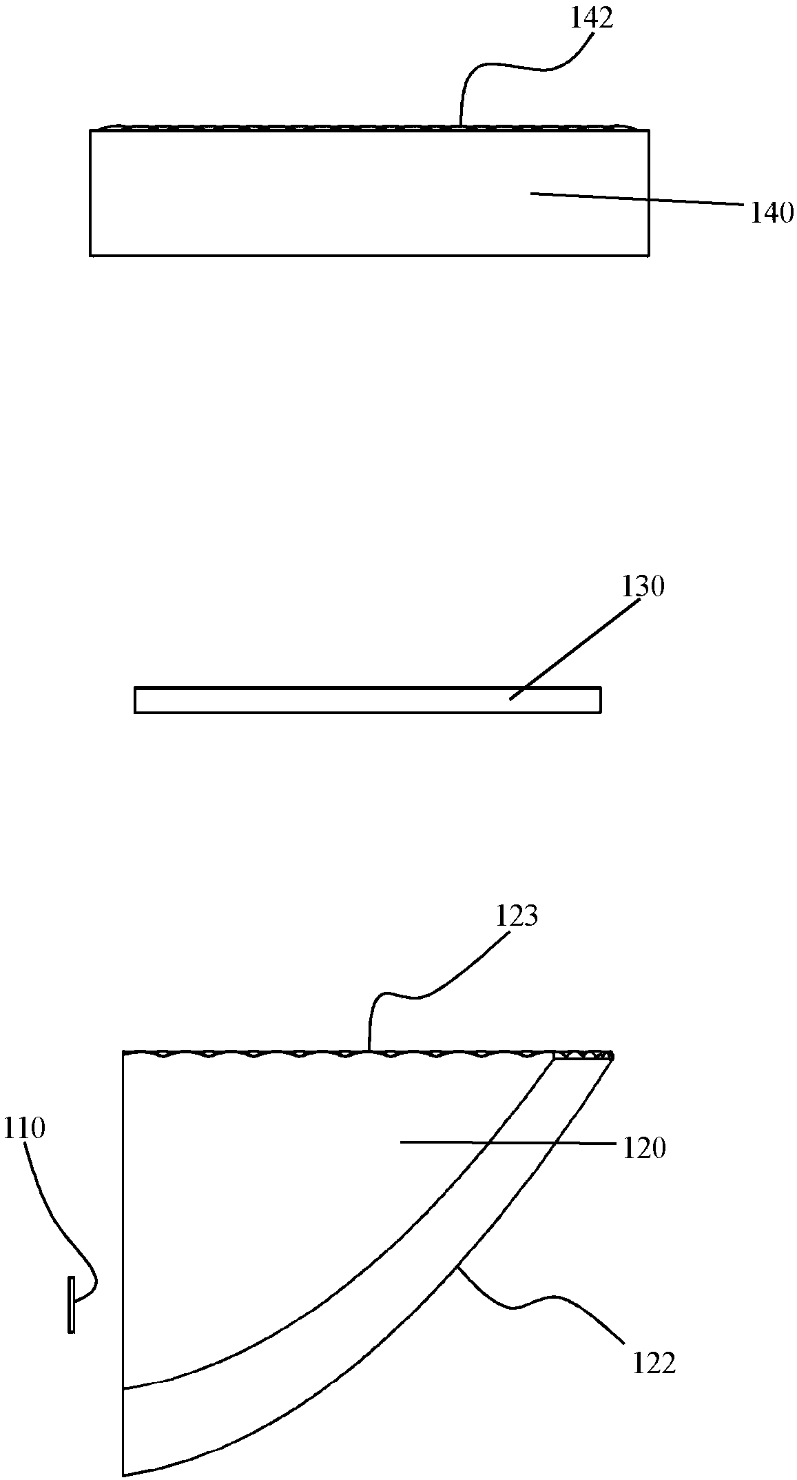
[0086] A kind of multi-channel optical projection module involved in the present invention, the official exploded diagram of its embodiment 1 is as follows figure 2 As shown, its isometric exploded view is shown as image 3 As shown, its cross-section is shown in Figure 4 shown. It is composed of a single-chip LED light source 110 , a free-form compound prism 120 , a patterned film 130 , and a back-end fly-eye lens 140 .

[0087] The single-chip LED light source 110 in the first embodiment is a high-power LED with a watt-level single chip, which is a flat-head LED or a ball-head LED, and is white or colored.

[0088] The free-form surface composite prism 120 of the present embodiment 1, its three views are as follows Figure 5 shown. It combines a free-form surface total reflection collimating prism with a large numerical aperture and a front fly-eye lens 123 . The large numerical aperture free-form surface total reflection collimating prism is composed of a concave sur...

Embodiment 2

[0095] In the multi-channel optical projection module involved in the present invention, the front-end fly-eye lens, the pattern film, and the rear-end fly-eye lens can be assembled together in the form of sandwich biscuits, as in Embodiment 2.

[0096] The multi-channel optical projection module of the present embodiment 2, its cross-sectional view is as follows Figure 12 As shown, it consists of a single-chip LED light source 210 , a free-form surface total reflection prism 220 , a front-end fly-eye lens 230 , a pattern film 240 , and a rear-end fly-eye lens 250 . The front-end fly-eye lens 230, the pattern film 240, and the rear-end fly-eye lens 250 are bonded together by glue in the form of sandwich biscuits.

[0097] The free-form surface total reflection prism 220 of the second embodiment is composed of a concave surface 221, a total reflection free-form surface 222, and an upper horizontal output surface 223, and its numerical aperture N.A. is greater than 0.6. It per...

Embodiment 3

[0104] The present invention relates to a multi-channel optical projection module, an LED collimation system, which can adopt one or more aspherical lenses with large numerical aperture and a front-end fly eye lens, which can be combined with one of the aspheric lenses Use together, as present embodiment 3.

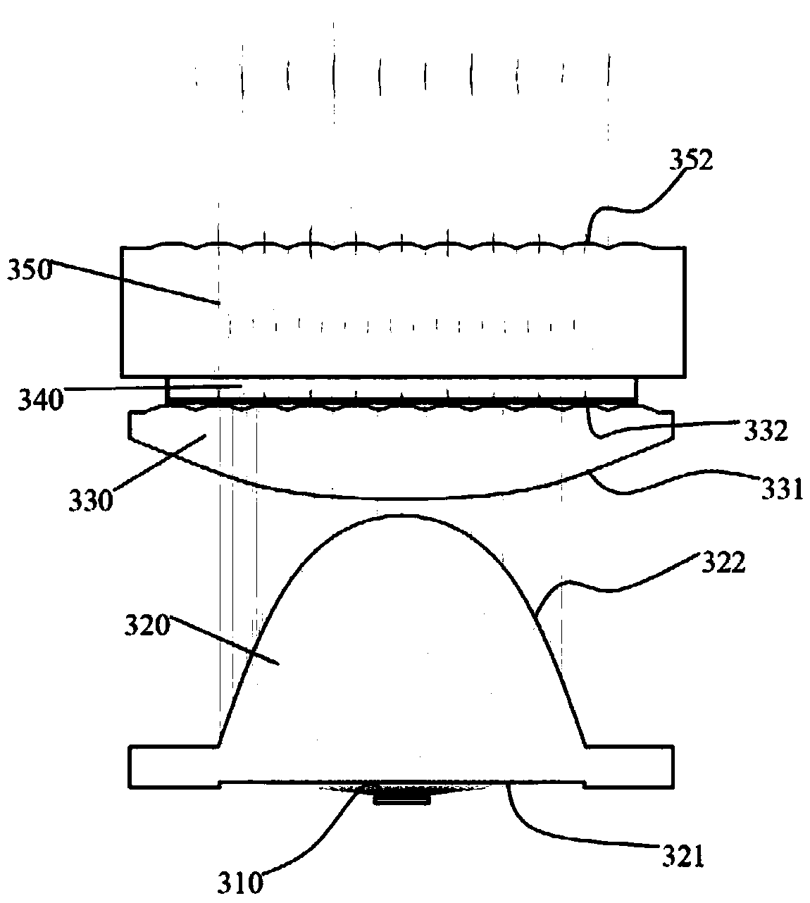
[0105] The multi-channel optical projection module of the present embodiment 3, its structural section diagram is as follows Figure 14 As shown, it consists of a single-chip LED light source 310 , a large numerical aperture aspheric lens 320 , a composite aspheric-fly-eye lens 330 , a patterned film 340 , and a back-end fly-eye lens 350 .

[0106] The composite aspherical-fly-eye lens 330 is formed by combining the aspheric lens 331 on the lower surface and the front-end fly-eye lens 332 on the upper surface.

[0107] The aspheric lens 320 with large numerical aperture has a lower surface 321 as a plane and an upper surface 322 as a high-order aspheric surface, which ca...


PUM


Abstract

The embodiment of the invention relates to an optical module structure of a pattern projection lamp used for automobile lighting, in particular to a multi-channel optical projection module, which is used for a welcome light of a car door and is used to project an artistic pattern with a special shape or create a structured light pattern that builds the welcome atmosphere. The optical module of thepattern projection lamp is characterized in that it is a multi-channel optical projection module adopting fly eye lenses (lens array), which includes a large numerical aperture free-form surface collimation system, a front-end fly eye lens, a pattern film, and a rear-end fly eye lens. The multi-channel optical module is composed of at least two or more optical channels. Each optical channel projects an identical pattern and forms a clear and single pattern after being stacked in the distance.

Description

technical field [0001] Embodiments of the present invention relate to the technical field of optical imaging, and in particular to an optical module structure of a pattern projection light. Background technique [0002] This section introduces readers to background technologies that may be related to various aspects of the present invention, and it is believed that useful background information can be provided to readers, thereby helping readers to better understand various aspects of the present invention. Accordingly, it is to be understood that the descriptions in this section are for the purposes stated above and do not constitute admissions of prior art. [0003] The traditional fly-eye lens is mainly used in the lighting system, which includes: uniform illumination for the light engine system of the projector, which uniformly illuminates DLP (Digital Light Processor) through one or two fly-eye lenses, LCOS (Liquid Crystal Display on Silicon Substrate) ) and other micr...

Claims


Application Information

Patent Timeline
IPC IPC(8): G03B21/20G02B27/30
CPCG02B27/30G03B21/2033G03B21/208
Inventor 郎欢标
Owner DONG GUAN LONGIDEAL IND CO LTD
Why Eureka
Try Eureka