Pulse field ion migration tube

A technology of ion transfer tube and pulse field, which is applied in the direction of particle separation tube, discharge tube, method of using particle spectrometer, etc., can solve the problems of electric field distortion, increase the cutting width of ion gate, etc., and achieve the effect of improving resolution

Active Publication Date: 2018-05-29
DALIAN INST OF CHEM PHYSICS CHINESE ACAD OF SCI
View PDF3 Cites 4 Cited by
  • Summary
  • Abstract
  • Description
  • Claims
  • Application Information

AI Technical Summary

Problems solved by technology

This diffusion causes the distortion of the electric field in the reaction zone and the migration zone adjacent to the ion gate, incr...

Method used


Image

  • Pulse field ion migration tube
  • Pulse field ion migration tube

Examples


Embodiment 1

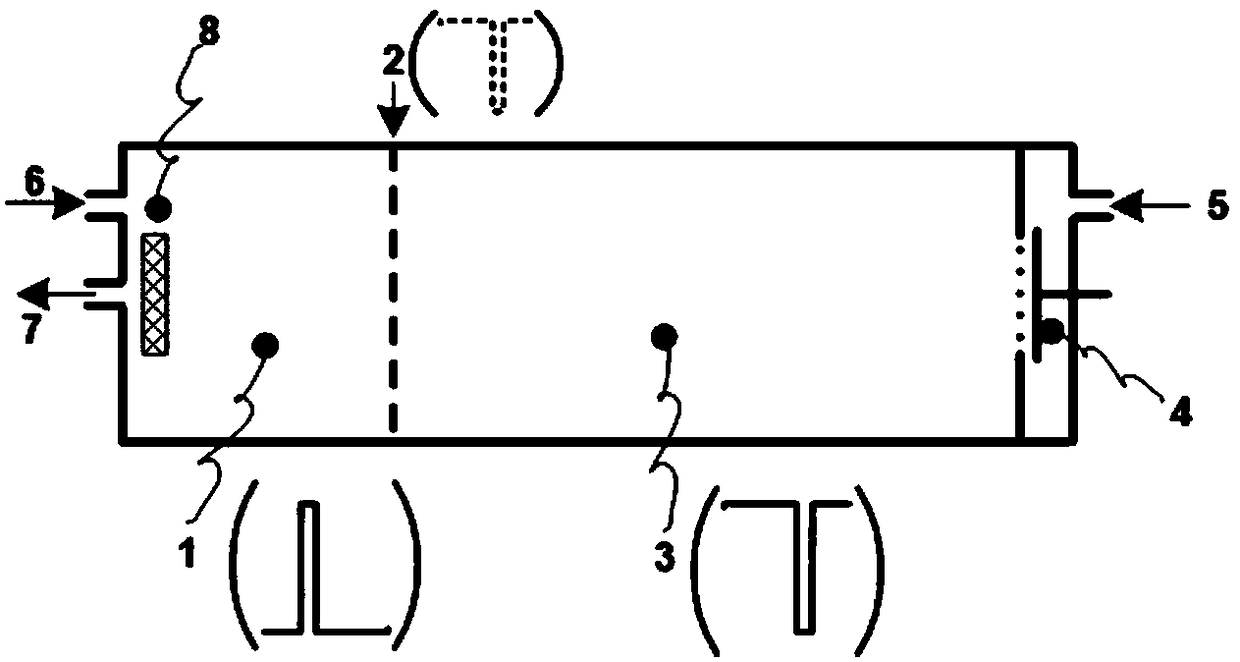
[0026] A pulsed field ion transfer tube is a hollow columnar cavity, and the ion source 8 of the reaction ion generating device and the Faraday disk 4 of the ion receiving device are respectively arranged at both ends of the cavity; the ion source and the Faraday disk are arranged inside the cavity Gate 2 divides the inner part of the cavity into two areas, wherein the ionization zone 1 is formed between the ion source and the ion gate, and the migration zone 3 is formed between the ion gate and the Faraday disk; both the ionization zone and the migration zone are formed by a ring-shaped plate electrode and a plate Shaped annular insulators are stacked alternately;

[0027] During ion implantation, the ion gate 2 is opened, and pulse voltages are applied to the electrodes in the ionization region 1 and the migration region 3 respectively, forming periodic pulsed electric fields in the ionization region 1 and the migration region 3 respectively. At this time, the electric field ...


PUM


Abstract

The invention provides a new technology for enhancing the ion utilization efficiency in the ion migration tube ionization region, and particularly provides a pulse field ion migration tube. A pulse varying electric field is applied to the ionization region and the migration region of the ion migration tube so that the electric field in the ionization region can be enhanced and the electric field in the migration region can be reduced at the moment of opening of the ion gate, all the ions in the ionization region can be injected into the migration region and spatial focusing compression is performed on the ion groups by using the difference of the electric field intensity of the ionization region and the migration region and thus the sensitivity of the ion migration tube can be greatly enhanced and the ion migration tube is enabled to have great resolution capacity.

Description

technical field [0001] The invention is a new technology for improving ion utilization efficiency in the ionization region of an ion transfer tube, specifically a pulse field ion transfer tube. By applying a pulse-changing electric field to the ionization region and the migration region of the ion transfer tube, at the moment the ion gate is opened, the electric field in the ionization region is increased and the middle electric field in the migration region is reduced at the same time, so that all the ions in the ionization region are injected into the migration region. In the region, the difference in the electric field strength between the ionization region and the migration region is used to focus and compress the above-mentioned ion clusters in space, thereby greatly improving the sensitivity of the ion transfer tube, and at the same time ensuring that the ion transfer tube has better resolution. Background technique [0002] The ion gate is an important component of th...

Claims


Application Information

Patent Timeline
IPC IPC(8): H01J49/00
CPCH01J49/0027H01J49/0031
Inventor 陈创李海洋黄卫陈红王卫国
Owner DALIAN INST OF CHEM PHYSICS CHINESE ACAD OF SCI
Why Eureka
Try Eureka