Thermal management device, system and method of fuel cell stack

A fuel cell stack, fuel cell stack technology, applied in fuel cell heat exchange, fuel cells, fuel cell additives, etc., can solve the problems of system vibration, affecting the working performance of control elements and control elements, and large temperature fluctuations , to achieve the effect of easy filling and replacement

Pending Publication Date: 2018-05-29
TSINGHUA UNIV
View PDF5 Cites 20 Cited by
  • Summary
  • Abstract
  • Description
  • Claims
  • Application Information

AI Technical Summary

Problems solved by technology

At the same time, the collapse of a large number of bubbles will lead to large pressure fluctuations caused by local high pressure, which will cause the system to vibrate, which will affect the control components and the working performance of the control components
During the test, it was found that the original structure would cause a large number of air bubbles to appear at the inlet or outlet of the stack, resulting in turbulent flow or swirl in the pipeline, and due to the hysteresis of the thermostat opening, short-term excessive temperature and relatively large temperature fluctuations occurred. big case

Method used


Image

  • Thermal management device, system and method of fuel cell stack
  • Thermal management device, system and method of fuel cell stack
  • Thermal management device, system and method of fuel cell stack

Examples


Embodiment 1

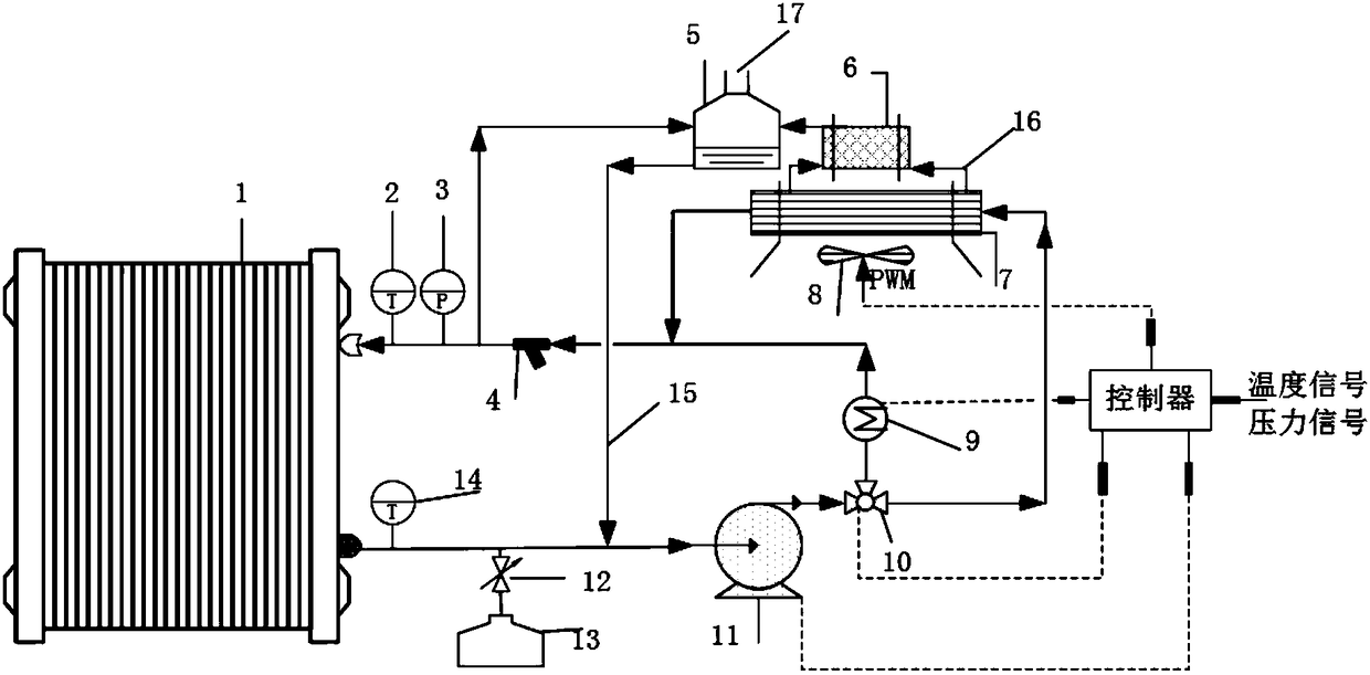
[0054] This embodiment combines image 3 , illustrating the working process of the cooling system for fuel cell stack thermal management:

[0055] In the embodiment of the present invention, when the temperature of the cooling liquid is lower than the preset temperature range, the cooling liquid is discharged from the cooling liquid outlet of the fuel cell stack, pressurized by the water pump, passes through the needle valve mechanism, and is discharged from the cooling liquid inlet of the fuel cell stack. Perform endothermic cooling of the fuel cell stack. If there are bubbles in the coolant, when the coolant circulates to the coolant inlet of the fuel cell stack, the bubbles will be discharged from the exhaust pipe to the water tank, and then discharged from the exhaust port at the upper end of the water tank. This process can be referred to as a small cycle.

[0056] When the temperature of the coolant is within the preset temperature range, the coolant is discharged from ...

Embodiment 2

[0060] to combine image 3 , this embodiment illustrates the composition of the fuel cell stack thermal management system: including: fuel cell stack 1, radiator 7, fan 8, water pump 11, electronic three-way valve 10, deionization tank 6, water supply tank 5, controller, filter Device 4, heating rod 9, temperature sensor 2 and pressure sensor 3. Using an electronic three-way valve 10 to adjust the large and small circulation of the cooling flow path can quickly change the opening of the three-way valve 10 according to the change of water temperature. Excessive temperature and pressure fluctuations effectively avoid damage to the interior of the stack caused by excessive water temperature. The replenishing water tank 5 can be used to remove the gas in the pipeline, and can also be filled with deionized water from the exhaust pipeline 16, which is convenient and quick to operate. A heating rod 9 is installed in the small circulation pipeline, which is used when starting the el...

Embodiment 3

[0062] This embodiment combines image 3 , Composition of fuel cell stack thermal management system: including:

[0063] Stack 1;

[0064] The exhaust pipeline, including two situations of small circulation and large circulation, is connected with the water tank.

[0065] The deionization tank 6 is connected in parallel with the radiator 7 and installed in the exhaust pipeline of the radiator 7 .

[0066] The water tank 5 is installed on the top of the radiator 7, and is used for filling deionized water and removing gas in the pipeline.

[0067] Electronic three-way valve 10 is used to control large and small circulation.

[0068] Heating rod 9 is installed in the small circulating water circuit and is used for cold start.

[0069] The fan 8 is controlled by a PMW (Pulse Width Modulation, Pulse Width Modulation) signal, and can be infinitely variable according to the temperature change of the water.

[0070] The controller is used to receive signals from the sensors and c...


PUM


Abstract

The invention proposes a thermal management device, system and method of a fuel cell stack. The device comprises a pipeline mechanism, a cooling liquid inlet, a control mechanism and a needle valve mechanism, wherein the pipeline mechanism penetrates through the fuel cell stack and is connected with a water box, a heat sink and a water pump, the cooling liquid inlet is used for circularly coolinga cooling liquid discharged out of a cooling liquid outlet of the fuel cell stack and then transmitting the cooling liquid to the fuel cell stack, the control mechanism is connected with a data acquisition device and is used for determining a temperature of the cooling liquid according to a temperature signal acquired by a data acquisition device and controlling opening degree of a needle valve according to the temperature signal so that the temperature of the cooling liquid is within a preset temperature range, the needle valve mechanism is arranged on a path between the water pump and the heat sink and is used for controlling flowing quantity of the cooling liquid of the heat sink according to a signal of the control mechanism, the pipeline mechanism comprises exhaust air ducts, the exhaust air ducts are respectively arranged on a path between the cooling liquid inlet of the fuel cell stack and the water box and on a path between a deionized water tank and the water box and are usedfor transmitting bubbles in the cooling liquid in the pipeline mechanism to the water box.

Description

technical field [0001] The invention relates to the technical field of thermal management of fuel cells, in particular to a fuel cell stack thermal management device, system and method. Background technique [0002] Fuel cell (such as proton exchange membrane fuel cell (PEMFC)) power generation is rapidly catching up and entering the stage of industrial scale application, and will become the fourth generation of power generation in the 21st century after thermal power, hydropower, and nuclear power. The dynamics of fuel cells The performance and service life are greatly affected by the intake air humidity, intake air flow and temperature, and a large amount of heat will be generated during the working process to be dissipated. At the same time, the greater the power, the more heat the engine will generate, and the design needs to meet the requirements of high power Cooling system for engine cooling requirements; [0003] Therefore, it is particularly important to develop an...

Claims


Application Information

Patent Timeline
Patent Type & Authority Applications(China)
IPC IPC(8): H01M8/04007H01M8/04029H01M8/04701
CPCH01M8/04007H01M8/04029H01M8/04723Y02E60/50
Inventor 张钦国李建秋徐梁飞欧阳明高郭迪江宏亮
Owner TSINGHUA UNIV
Why Eureka
Try Eureka