Logic circuit and operating method thereof

A technology of logic circuit and operation method, applied in the direction of logic circuit, electrical components, reliability improvement and modification, etc., can solve the problems of high computational complexity, high circuit power consumption, high logic calculation bit error rate, and reduce the bit error rate , to achieve write and read functions, to avoid the effect of competitive risk

Active Publication Date: 2018-05-29
HUAZHONG UNIV OF SCI & TECH
View PDF3 Cites 26 Cited by
  • Summary
  • Abstract
  • Description
  • Claims
  • Application Information

AI Technical Summary

Problems solved by technology

[0003] Aiming at the defects of the prior art, the purpose of the present invention is to provide a logic circuit and its operation method, aiming to solve the problem of high bit error rate of logic calculation caused by competition risk in the traditional logic gate circuit, and the existing memristor-based In the cascading process of the logic gate circuit of the device, the conversion circuit is frequently used, resulting in high computational complexity and high circuit power consumption.

Method used


Image

  • Logic circuit and operating method thereof
  • Logic circuit and operating method thereof
  • Logic circuit and operating method thereof

Examples


Embodiment Construction

[0034] In order to make the object, technical solution and advantages of the present invention clearer, the present invention will be further described in detail below in conjunction with the accompanying drawings and embodiments. It should be understood that the specific embodiments described here are only used to explain the present invention, not to limit the present invention.

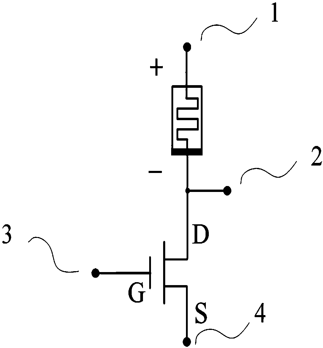
[0035] Such as figure 2 As shown, the logic circuit provided by the present invention includes: a resistive variable unit and an NMOS transistor, the negative pole of the resistive variable unit is connected to the drain of the NMOS transistor, and a port is drawn here, connected to the positive pole of the resistive variable unit, the NMOS transistor The gate and source form a four-terminal structure. The four ports are respectively the first input end 1 , the second input end 3 , the ground end 4 and the cascade end 2 .

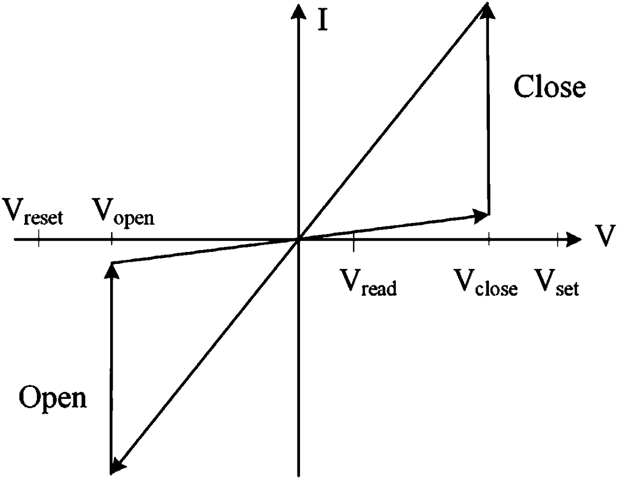
[0036] When a positive voltage pulse greater than the first threshold is...


PUM


Abstract

The invention discloses a logic circuit and an operating method thereof. The logic circuit comprises a resistive switching unit and a field effect transistor, wherein the positive electrode of the resistive switching unit is used as a first input terminal, the negative electrode of the resistive switching unit is connected with the drain of the field effect transistor to act as a cascade terminal,the gate of the resistive switching unit is used as a second input terminal, and the source of the field effect transistor is used as a ground terminal; the first input terminal is used to apply a logic operating voltage; the cascade terminal is used for an external circuit; the second input terminal is used to apply a logic input voltage signal; and the ground terminal is used for grounding. When a logic operation is performed, a Set voltage is applied to the positive electrode of the resistive switching unit, the source of the field effect transistor is grounded, the gate of the field effect transistor is connected with an input signal, the initial resistance state of the resistive switching unit is used as another input, and thus an IMP logic function can be realized; and various logicoperations such as NAND can be completed in the structure through multiple steps of repetitive operations or the external circuit. The scheme of the invention can realize a variety of logic functions, and is also simple to operate and easy to control.

Description

technical field [0001] The invention belongs to the field of digital circuits, and more specifically relates to a logic circuit and an operation method thereof. Background technique [0002] Memristor is considered as the fourth basic circuit element besides resistors, capacitors, and inductors. It can memorize the amount of charge flowing through it, and its resistance value can be changed by controlling the change of current. The high-resistance state and low-resistance state of memristor can be used to store "0" and "1" for information storage, and has the advantages of non-volatility, low power consumption, high speed, and high integration. In addition, memristors have also been proposed to implement logic operations. For logic operations in traditional CMOS logic gate circuits, the carriers of both input and output signals are voltages, which cannot be stored in real time and are volatile when power-off; and because both input signals are voltages, there is a risk of c...

Claims


Application Information

Patent Timeline
Patent Type & Authority Applications(China)
IPC IPC(8): H03K19/003H03K19/0948
CPCH03K19/003H03K19/0948
Inventor 李祎程龙周亚雄王卓睿缪向水
Owner HUAZHONG UNIV OF SCI & TECH
Why Eureka
Try Eureka